1Hearth & Home Technologies • GFK-210 Blower System Instructions 2206-938 Rev. H • 7/11
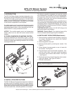
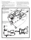
Figure 1
GFK-210 Blower System
- Installation and Operating Instructions -
1.0 INTRODUCTION
The GFK-210 Blower System has been designed to circu-
late room air through the fi replace to enhance heat output.
The GFK-210 blower system operates on 120 VAC, 60 Hz
power. This is available through a receptacle in the factory
installed power cord assembly. The power cord is located
in the controls compartment of the fi replace.
A variable speed control is provided with the blower system
to provide quiet forced air fl ow at the desired speeds. A
temperature sensor switch, which automatically turns the
blower ON/OFF, is also provided with this kit.
NOTICE: The variable speed control and temperature
sensor switch are not used with some remote control
systems.
2.0 CHECK CONTENTS OF SHIPPING CARTON
Compare CONTENTS OF CARTON in Figure 1 with the
actual parts received. If any parts are missing or damaged,
contact your dealer before starting installation. Do not install
a damaged blower kit.
3.0 INSTALLATION PRECAUTIONS
The GFK-210 Blower Kit is tested and safe when installed in
accordance with this installation manual. It is your responsi-
bility to read all instructions before starting installation and to
follow these instructions carefully during installation to assure
maximum benefi t from, and safe operation of, the blower.
CONTROL
NUT
060-814
CONTROL
KNOB
100-512
WING
NUT
060-872
TEMPERATURE
SENSOR
SWITCH
046-018A
VARIABLE SPEED CONTROL
2206-800
BLOWER CORD
2206-068
NOTE: Install the blower using the access panel located on
the back side of the appliance.
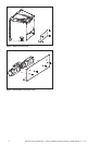
4.0 INSTALLING THE BLOWER (Metal Inserts)
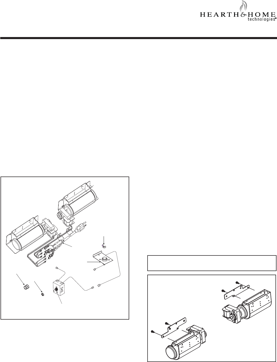
1. Remove factory-installed blower brackets by removing
four screws. Brackets are only used for the FireBrick
inserts. See Figure 2.
2. Remove appliance from wall.
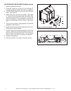
3. Remove access panel by removing four screws. See
Figure 3.
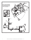
4. Screw blowers to access panel on rear of insert with
four screws. See Figure 4.
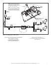
5. Plug the blower cord into the blower receptacle. Con-
nect the white, black, and green spade connectors
from blower cord harness to each blower. See Figure
1 and Figure 6.
6. Bundle and zip tie any wires to keep them from contact-
ing the fan blades. See Figure 6, Detail A.
7. Reinstall access panel.
This blower is carefully engineered and must be installed
only as specifi ed. If you modify it or any of its components,
you may cause a fi re hazard and will void the WARRANTY.
In addition, such action may void the coverage provided
by the owner's home insurance.
CAUTION: All wiring should be done by a qualifi ed electri-
cian and shall be in compliance with local codes and with
the National Electric Code ANSI/NFPA NO. 70-current (in
the United States), or with the current CSA C22.1 Canadian
Electric Code (in Canada).
CAUTION! DO NOT connect 110-120 VAC wiring to the
gas control valve of the fi replace.
WARNING! Risk of Shock! Turn electrical power off at
the circuit breaker before beginning this installation.
Figure 2 Remove Blower Brackets