MAINTENANCE
29
F−98857
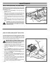
HOW TO LEVEL THE MOWER HOUSING
If the mower housing is level, the blade will cut easier and the lawn
will look better.
WARNING: Before you make an inspection, adjust-
ment, or repair to the unit, disconnect the wire to the
spark plug. Remove the spark plug wire to prevent
the engine from starting by accident.
1. Make sure the unit is on a hard level surface.
2. Check the air pressure in the tyres. If the air pressure is incor-
rect, the mower housing will not cut level. Make sure the tyres
are inflated to 14 PSI. (1 BAR).
3. Move the lever for the blade rotation control to the
DISENGAGE position. Move the lift lever to the number “4” cut-
ting height position.
4. There are two adjustment procedures below that will level the
mower housing.
THE FRONT TO BACK ADJUSTMENT
Before the height of the mower housing is measured, understand
that the position of the blades in the mower housing are not the same
in the front as they are in the back.
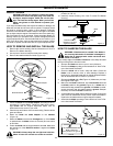
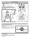
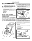
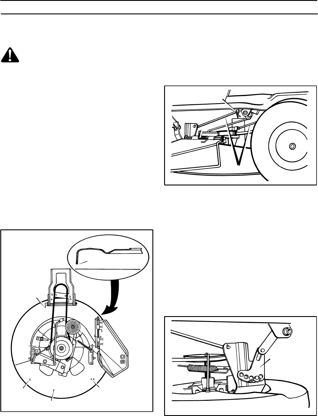
There are measuring points on the mower housing indicated by
small round dimples (or X marks) on the front and rear, left and right
sides of the mower housing (Figure 24). To determine if an
adjustment is needed, use a ruler and measure the distance from
the level surface to the bottom of the mower housing. In correct
adjustment, the front of the mower housing at point B will be from
0” to 1/2” (0 mm to 12 mm) lower than the back of the mower housing
at point D.
SIDE VIEW
Measure from the bottom
of the mower housing.
LEVEL SURFACE
B
A
D
C
Figure 24
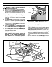
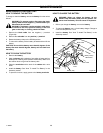
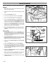
1. Disconnect both adjuster rods from the adjuster rod
brackets (Figure 25).
2. Turn the adjustable nut clockwise to lower the front or counter-
clockwise to raise the front of the mower housing.
3. Connect the left adjuster rod to the adjuster rod bracket.
Check the housing for the correct adjustment. Fasten the ad-
justable nut with the washer and hair pin.
4. On the right side, turn the adjustable nut until the adjustable nut
is aligned with the hole in the adjuster rod bracket. Fasten the
adjustable nut with the washer and hair pin.
Adjuster Rod Bracket
Figure 25
Adjuster Rods
THE SIDE TO SIDE ADJUSTMENT
Use a ruler and measure the distance from the level surface to the
bottom of the mower housing. Measure from the locations indicated
by the small round dimples (or X marks) at points A and C. In correct
adjustment, the mower housing at points A and C must be within
1/4” (6 mm) of the same height. If the difference in the measurement
is more than 1/4” (6 mm), adjust as follows.
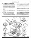
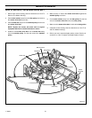
1. Disconnect the adjuster plate from the mower housing
(Figure 26).
2. Move the adjuster plate to the front to raise or to the back to
lower the side of the mower housing. On some adjuster plates
the holes have numbers. To raise the mower housing, move to
a higher number.
3. Connect the adjuster plate.
4. Check the housing for the correct adjustment. If necessary, re-
peat the adjustment.
Adjuster Plate
Figure 26


