


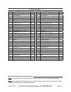

SKU 65076 For technical questions, please call 1-800-444-3353. Page 8
cleaned even if they are new or ap-
pear clean.
Allow all pieces to dry completely.4.
Place fresh, clean bearing grease in 5.
the packer.
With the grease-lled bearing packer 6.
in one hand and the bearing in the
other, press the bear ing into the
grease, forcing the grease inside the
slots in the bearing, continue doing
this until every slot in the bearing is
completely full of grease.
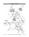
Hub and Wheel Assembly
Put a Seal (59) and Bearing (49) on 7.
the Axle and then put the Tire on the
Axle.
With each Tire in place, add a Wash-8.
er (50) and a Spindle Nut (51) onto
the ends of the Axles. Tighten the
Spindle Nuts to 20-25 ft. pounds and
turn each tire several times to seat
the bearing. Back off the Spindle Nut
one half turn. Insert a Cotter Pin (25)
through both the Axle and the Spindle
Nut and bend the end of the Pin
back to hold it in place. Last, tap on a
Wheel Cap (61).
Connecting the Rail Assembly (2) to the
Oil Tank Assembly (10B)
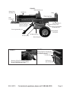
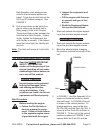
Insert the Front Leg Assembly (11) 9.
into the bracket on the Oil Tank As-
sembly (10B). Insert the remaining
Hex Bolt (16) through the hole in the
middle of the bracket of the Oil Tank
Assembly (10B). Secure it with a
Hex Nut (17). Refer to the Hex Nut
(17) attached to the Hex Bolt (16) at
the top of the Front Leg Assembly
(11) in FIGURE 1.
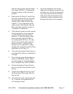
When moving the Log Splitter, re-10.
move the Push Pin (26) and Hair Pin
Clip (29) and lift the Front Leg As-
sembly up so that it is parallel to the
Rail Assembly (2). Then, replace the
Push Pin and Hair Pin Clip into the
Horizontal Transport Hole shown just
above the Oil Plug (37), in FIGURES
1 and 2.
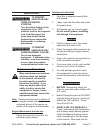
To connect the Rail Assembly to the 11.
Oil Tank Assembly (10B), insert a Hex
Bolt (16) into the middle hole of the
“L” shaped bracket on the Oil Tank
Assembly. Secure it with a Hex Nut
(17). Refer to the Hex Nut (17) at-
tached to the Hex Bolt (16) just above
the tire in FIGURE 1. Insert the Push
Pin (26) through the hole, as shown
in FIGURE 3.
In FIGURES 1 and 2, the Rail As-12.
sembly (2) is shown in Horizontal
mode for operation and travel (as
mentioned above, the Front Leg As-
sembly must be secured up in the
horizontal position when travelling)
Transportation
DO NOT TRANSPORT THE LOG 13.
SPLITTER ON PUBLIC ROADS.
The Log Splitter is not certied by the
D.O.T. for use on Public roads.
When transporting the Log Splitter, 14.
make sure the hitch (not included) is
compatible with the Hitch Coupler (9).
Follow all of the safety warnings for
towing in the vehicle manufacturer’s
manual. Always use the Safety Chain
with Hook (4) during towing. Do not
tow the Log Splitter at speeds above
45 MPH. As mentioned in step 10,
travel with the Front Leg Assembly
(11) in the horizontal position. The