


14
Installation Manual For Wire Controller
52¡ 0.2
10.45
Screw holes
5.3
Bracket
Wire controller
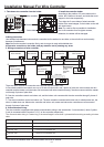
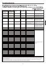
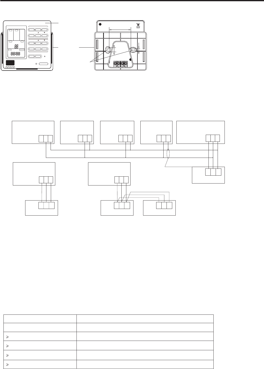
5. Wiring connections of wire controller:
There are three methods to connection wire controller and the indoor units:
A.One wired controller can control max. up to 16 sets of indoor units, and 3 pieces of polar wire must connect the wire
controller and the master unit (the indoor unit connected with wire controller directly), the others connect with the master
unit through 2 pieces of polar wire.
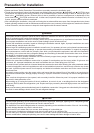
B. One wire controller controls one indoor unit, and the indoor unit connects with the wire controller through 3 pieces of
polar wire.
C. Two wired controllers control one indoor unit. The wire controller connected with indoor unit is called master one, the
other is called slave one. Master wire controller and indoor unit; master and slave wire controllers are all connected
through 3 pieces of polar wire.
6. Communication wiring:
The wire controller is equipped with special communication wiring in the accessories. 3-core terminal (1-white 2-yellow
3-red) is connected with the terminal A, B, C of wire controller respectively.
A B C
Indoor 16
Indoor 15Indoor NIndoor 2Indoor 1
Wire controller
(master unit)
A B C
Control wiring
of wire
controller,
polar.
A
Wire controller Wire controller Wire controller Wire controller
Wire controller
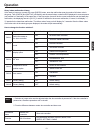
The communication wiring is 5 meter long; if the actual length is more than it, please distribute wiring according to below
table:
Communication wiring length(m) Dimensions of wiring
< 100 0.3mm
2
x3-core shielded wire
100 and <200 0.5mm
2
x3-core shielded wire
200 and <300 0.75mm
2
x3-core shielded wire
300 and <400 1.25mm
2
x3-core shielded wire
400 and <600 2mm
2
x3-core shielded wire
*One side of the shielded sheet of communication wire must be earthed.
A B C A B C A B C A B C
Indoor 1
Wire controller
A B C
Wire controller
Polar wire
Indoor 1
Wire controller
A B C
Wire controller
Polar wire
A B C
Wire controller
Polar wire
BC
A B C A B C
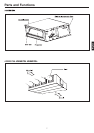
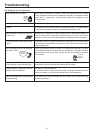
1. Take down wire controller from the holder
3.Wiring instruction
Use shielded wire between indoor and wire controller.And be earthed on one side, or the unit will not work normally
because of interference.
Note:Confirm the terminal connection firmly, and do not get in tough with shielded wire.
4.Place wire controller on the holder, and pay attention not to pressing any wires.
2. Install the controller holder
According to the position of 2 screw holes on the
holder, drill 2 holes on the wall, and strike the wood
stopper to the holes respectively.
Then align the 2 screw holes of wired controller
holder to the wood stopper, fix the holder on the wall
with wood screw.
Note:Try a wall as flat as possible for installation.
Don't use excessive force to tighten screws,
otherwise, the holder will be damaged.
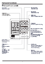
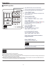
AUTO
FAN ONLY
COOL
DRY
HEAT
TES
FAN
AUTO
HIGH
LOW
FIX
CENTRAL
OPERATION
STANDBY
PRE-HEAT
DEFROST
FILTER
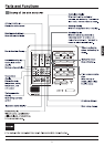
MODE
HEALTH
SWING
CHECK
UNIT NO.
C
F
DEMAND
CEN. ADD.
SYS. ADD.
MANUAL
ROOM TEMP.
SET TEMP.
TIMER
VENTILATION
CLOCK UPDOWN
ON
OFF
DAILY
AUTO
RECOVERY
NORMAL
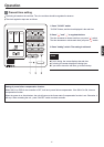
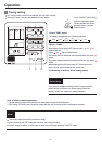
MODE FAN SWING
HEALTH
CLOCK
TIMER
CHECK FILTER
RESET
ON/OFF
SET RECOVERY
TEMP
TIME
MED