


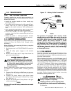
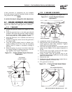
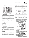

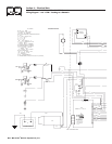

Figure 3.3 – Low Oil Pressure and
High Temperature Switches
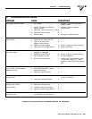
3.7.3 OVERCRANK
This feature prevents the generator from damaging
itself when it continually attempts to start and anoth-
er problem, such as no fuel supply, prevents it from
starting. The unit will crank and rest for a preset time
limit. Then, it will stop cranking, and the LED will
light indicating an overcrank failure. The
AUTO/OFF/MANUAL switch will need to be set to OFF
and then back to AUTO to reset the generator control
board.
NOTE:
If the fault is not repaired, the overcrank feature
will continue to activate.
3.7.3.1 Approximate Crank Cycle Times
• 15 seconds ON
• 7 seconds OFF
• 7 seconds ON
• 7 seconds OFF
• Repeat for 45 seconds
Approximately 90 seconds total
3.7.4 OVERSPEED
This feature protects the generator from damage by
shutting it down if it happens to run faster than the
preset limit. This protection also prevents the gener-
ator from supplying an output that could potentially
damage appliances connected to the generator cir-
cuit. Contact the nearest Generac Authorized Dealer
if this failure occurs.
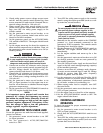
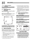
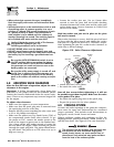
4.1 FUSE
The generator panel’s 15 amp fuse (Figure 4.1) protects
the DC control circuit against overload. The fuse is
wired in series with the battery output lead to the panel.
If the fuse element has melted open, the engine cannot
crank or start. Replace the fuse using only an identical
15-amp replacement.
The generator panel’s 5 amp fuse protects the battery
charge circuit against overload. If the fuse element has
melted open, battery charging capability will not be pos-
sible. Replace the fuse using only an identical 5 amp
replacement. To remove fuse, push cap down and
rotate counterclockwise.
Figure 4.1 – Generator Control Panel
4.2 CHECKING THE ENGINE
OIL LEVEL
For oil capacities, see “Specifications,” Section 1.5.
For engine oil recommendations, see Section 4.3.1.
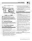
To check the engine oil level, proceed as follows
(Figure 4.2):
1. Start the generator by moving the Auto/
Off/Manual switch to the MANUAL position. Allow
it to run for a short while and then shut it down
by moving the switch to the OFF position.
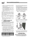
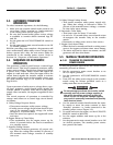
Figure 4.2 — Oil Dipstick and Fill, 7 kW
2. Remove the dipstick and wipe it dry with a
clean cloth.
3. Install the dipstick; then, remove it again. The oil
level should be at the dipstick “Full” mark. If nec-
essary, add oil to the “Full” mark only. DO NOT
FILL ABOVE THE “FULL” MARK.
Never operate the engine with the oil level
below the “Add” mark on the dipstick. Doing
this could damage the engine.
!
Oil Dipstick and Fill
HIGH TEMP.
OVER SPEED
LOW OIL
SYSTEM SET
OVER CRANK
MAN.
SET
OFFAUTO
15A
FUSE
EXERCISE
TIME
R
POWER SYSTEMS, INC.
Locate your nearest dealer at:
R
FUSE
5A
EXERCISE RNOT SET
NOUTILITYSE NSE
4FLASHING RED LEDS=
FLASHINGGREEN LED=
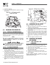
Oil Filter
Oil
Drain
Hose
Low Oil Switch
High Temp Switch
L
o
o
s
e
n
Section 4 — Maintenance
Guardian Air-cooled 7 kW, 12 kW and 15 kW Generators
Generac® Power Systems, Inc. 17