


Section 3 — Operation
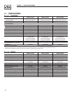
Air-cooled 7 kW, 12 kW and 15 kW Generators
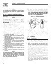
5. Remove load, stop engine, loosen the idle adjust
screw and reconnect the idle spring.
6. Using a hand, push the governor arm to the
closed throttle position. Make sure the idle spring
does not stretch at all.
7. Restart the unit.
8. Slowly turn the idle adjust screw to adjust the no-
load idle frequency to 63-63.5 Hz.
9. The governor is now set.
2.7.3 ADDITIONAL CORROSION
PROTECTION
Periodically spray all engine linkage parts and brack-
ets with corrosion inhibiting spray such as WD-40 or
a comparable product.
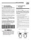
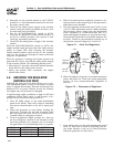
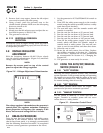
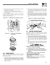
2.8 VOLTAGE REGULATOR
ADJUSTMENT
With the frequency between 62-63.5 Hertz, slowly
turn the slotted potentiometer (Figure 2.6) until line
voltage reads 244-252 volts.
NOTE:
Remove the access panel on top of the control
panel to adjust the voltage regulator.
Figure 2.6 – Voltage Adjustment Potentiometer
NOTE:
The voltage regulator is housed above the generator's
control panel. The regulator maintains a voltage in
direct proportion to frequency. For example, at 62
Hertz, line-to-neutral voltage will be 124 volts.
3.1 BREAK-IN PROCEDURE
Once the unit has been installed, with utility power
connected to the transfer switch, and all electrical
checks have been made, it is strongly recommended
that the following “Break-in Procedure” be completed
to ensure correct generator operation in the future.
1. Set the generator’s AUTO/OFF/MANUAL switch to
AUTO.
2. Turn OFF the utility power supply to the transfer
switch using the means provided (such as a utility
main line circuit breaker).
3. The unit will start, and the transfer switch will
transfer to standby.
4. Run the unit for one hour at 25 percent load.
5. Run the unit for one hour at 50 percent load.
6. Run the unit for one hour at 75 percent load.
7. Run the unit for one hour at 100 percent load.
8. Turn ON the utility power supply to the transfer
switch, which will allow the transfer switch to
transfer back to utility power. The unit will con-
tinue to run for one minute and then shut down.
9. Allow the unit to cool.
10. Drain the oil and remove the oil filter. Replace
the oil filter according to Section 4.4, “Changing
the Oil Filter”. Replace the oil with synthetic oil
as recommended in Section 4.3, “Changing the
Engine Oil”.
11. The generator is now ready for service.
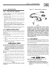
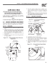
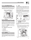
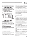
3.2 USING THE AUTO/OFF/MANUAL
SWITCH (FIGURE 3.1)
3.2.1 “AUTO” POSITION
Selecting this switch position activates fully automatic
system operation. It also permits starting and exercising
the engine every seven days with the setting of the exer-
cise timer (see Section 3.6). This position also is used
for remote starting, when it is set up.
3.2.2 “OFF” POSITION
This switch position shuts down the engine. This
position also prevents automatic operation.
3.2.3 “MANUAL” POSITION
Set the switch to MANUAL to crank and start the
engine. Transfer to standby power will not occur
unless there is a utility failure.
Figure 3.1 – Generator Control Panel
HIGH TEMP.
OVER SPEED
LOW OIL
SYSTEM SET
OVER CRANK
MAN.
SET
OFFAUTO
15A
FUSE
EXERCISE
TIME
R
POWER SYSTEMS, INC.
Locate your nearest dealer at:
R
FUSE
5A
EXERCIS ERNOT SET
N OUTILITYS ENSE
4FLASHIN G RED LEDS=
FLASHIN GGREEN LED=
14