


12 Generac
®
Power Systems, Inc.
5. Turn ON the utility power supply to the transfer
switch, using the means provided (such as a util-
ity main line circuit breaker).
6. Set the AUTO/OFF/MANUAL switch to AUTO. The
system is now ready for automatic operation.
7. Turn OFF the utility power supply to the transfer
switch.
With the AUTO/OFF/MANUAL switch at AUTO, the
engine should crank and start when the utility source
power is turned OFF. After starting, the transfer
switch should connect load circuits to the standby
side. Let the system go through its entire automatic
sequence of operation.
With the generator running and loads powered by
generator AC output, turn ON the utility power sup-
ply to the transfer switch. The following should
occur:
• After about six seconds, the switch should transfer
loads back to the utility power source.
• About one minute after retransfer, the engine
should shut down.
2.6 ADJUSTING THE REGULATOR
(NATURAL GAS ONLY)
Although the generator has been factory set to pro-
vide maximum power, it may be necessary in some
areas to adjust this setting. Because natural gas has
different BTU or power content across the country
the engine may not perform as designed.
If experiencing engine problems at high or full load
conditions follow these steps. It will require a fre-
quency meter to perform this procedure.
1. Turn off utility power to the main distribution
panel in the house. This can be done by switching
the service main breaker to the off or open posi-
tion.
2. Allow the generator to start. Before loading the
generator, confirm that the No Load Frequency,
with the roof open and door off, is set to 63-63.5
Hz. Transfer load to emergency circuits.
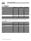
3. Turn on appliances, lights, pumps, etc., that are
on the emergency circuits in an attempt to fully
load the generator. Be cautious not to overload
the generator. Use the following chart as a guide:
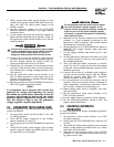
4. When full load has been achieved. Connect a fre-
quency meter to the output lugs of the generator’s
main line circuit breaker.
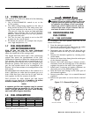
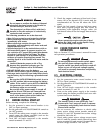
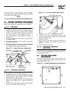
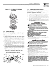
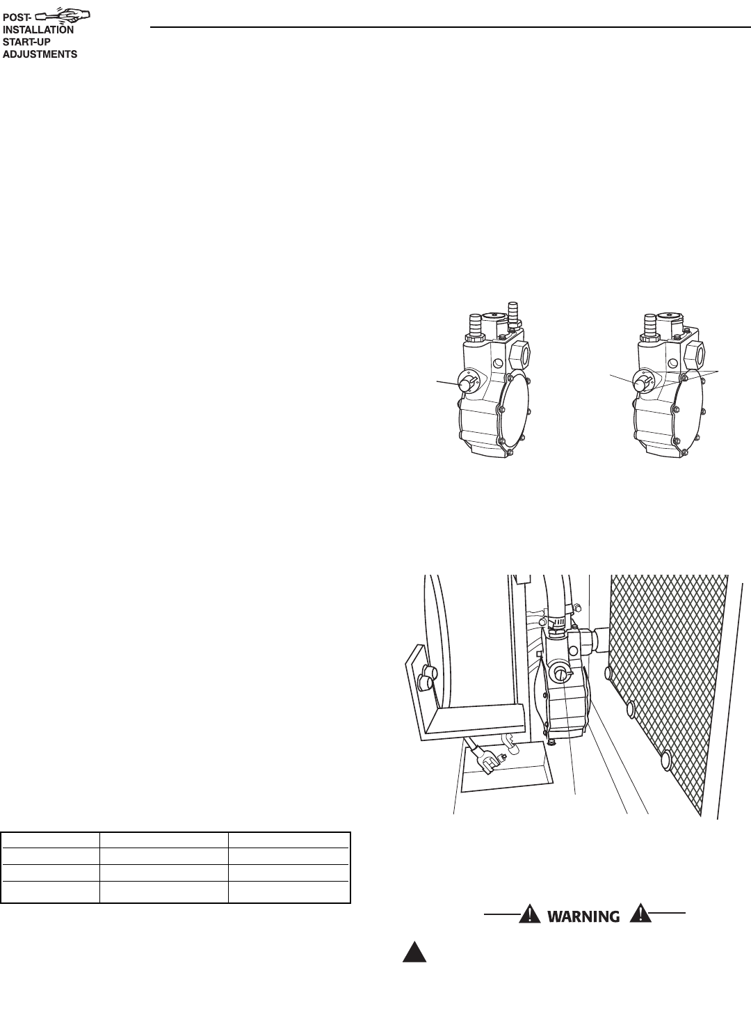
5. The fuel regulator is fitted with one (7 kW), or two
(12 & 15 kW) adjustment screws. While watching
the frequency meter, slowly turn the adjustment
screws clockwise or counterclockwise one at a
time until the highest frequency is read on the
meter. Only limited adjustment is available
between the set pins (7 kW only). Under no cir-
cumstances should any of the pins be removed
(Figures 2.1 and 2.2).
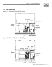
Figure 2.1 — Dual Fuel Regulators
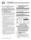
6. When the highest frequency is reached maximum
power has been set. From this point turn both
adjustment screws 1/4 turn counterclockwise.
The regulator is now set.
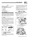
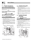
Figure 2.2 — Placement of Regulator
7. Turn utility power to the main distribution panel
back on. This can be done by switching the serv-
ice main breaker to the on or closed position.
Allow the generator to shut down.
Do not make any unnecessary adjustments.
Factory settings are correct for most applica-
tions. However, when making adjustments, be
careful to avoid overspeeding the engine.
!
Adjustment Screw
410
Adjustment
Screw
(One Side
Only)
Set
Pins
990
Adjustment
Screw
(Both sides)
Section 2 — Post Installation Start-up and Adjustments
Guardian Air-cooled 7 kW, 12 kW and 15 kW Generators
Unit 120 Volts 240 Volts
7 kW 50.0 amps 25.0 amps
12 kW 100.0 amps 50.0 amps
13 kW 108.3 amps 54.1 amps