


Generac
®
Power Systems, Inc. 13
Section 2 — Post Installation Start-up and Adjustments
Guardian Air-cooled 7 kW, 12 kW and 15 kW Generators
If this procedure or the equipment are not available,
locate the nearest Generac Guardian Dealer and they
can perform the adjustments.
NOTE:
A service fee may be charged for this adjustment.
2.7 ENGINE GOVERNOR ADJUSTMENT
If both AC frequency and voltage are correspondingly
high or low, adjust the engine governor as follows:
2.7.1 7 KW UNITS
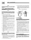
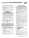
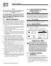
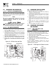
1. Loosen the governor clamp bolt (Figures 2.3).
2. Hold the governor lever at its wide open throttle
position, and rotate the governor shaft clockwise
as far as it will go. Then, tighten the governor
lever clamp bolt to 70 inch-pounds (8 N-m).
3. Start the generator; let it stabilize and warm up
at no-load.
4. Connect a frequency meter across the generators
AC output leads.
5. Turn the speed adjust nut to obtain a frequency
reading of 63 Hertz.
6. When frequency is correct at no load, check the
AC voltage reading. If voltage is incorrect, the volt-
age regulator may require adjustment.
Figure 2.3 — Engine Governor Adjustment
2.7.2 12 KW AND 15 KW UNITS
1. Loosen governor clamp bolt (See Figure 2.3).
2. Completely remove the idle spring.
3. With governor arm at wide open throttle position,
rotate governor shaft fully clockwise. Tighten
clamp bolt to 84 inch-pounds.
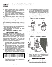
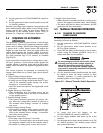
4. Start unit and apply full load. Use full load speed
adjust screw (Figure 2.4) to adjust frequency to
58 Hz.
5. Remove load, stop engine, loosen the idle adjust
screw and reconnect the idle spring.
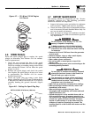
Figure 2.4 — Full Load Speed Adjust Screw
6. Using a hand, push the governor arm to the
closed throttle position. Make sure the idle spring
does not stretch at all.
7. Restart the unit.
8. Slowly turn the idle adjust screw to adjust the no-
load idle frequency to 63-63.5 Hz (with door
open).
9. The governor is now set.
2.7.3 ADDITIONAL CORROSION
PROTECTION
Periodically spray all engine linkage parts and brack-
ets with corrosion inhibiting spray such as WD-40 or
a comparable product.
2.8 VOLTAGE REGULATOR
ADJUSTMENT
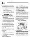
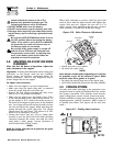
With the frequency between 62-63 Hertz, slowly turn
the slotted potentiometer (Figure 2.5) until line volt-
age reads 247-252 volts.
Figure 2.5 – Voltage Adjustment Potentiometer
◆
Full Load Speed Adjust Screw
◆
Governor Clamp Bolt
Governor
Shaft
(Rotate
Clockwise)
Idle Spring
No Load Idle
Adjustment Screw
◆