


NOTE: Balance must be maintained when
moving circuit locations from main electrical
distribution panel to emergency load center.
Circuit breaker positions alternate buss bars
vertically. Circuits sharing a neutral wire should
either be moved together to adjacent positions
in emergency load center or not moved. If you
are unsure of proper procedure or if your
installation differs from that described in this
guide, consult a licensed professional at this
time.
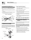
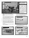
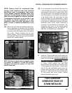
10a. Remove the main electrical distribution panel cover.
Remove appropriate size knockout from the bottom
or side of the main panel. (A 2-foot flexible conduit
is pre-wired from the transfer switch with built-in
load center). Remove threaded lock nut from
conduit coupling. Feed all wires through knockout
into main panel. Slip lock nut over wires and tighten
securely onto conduit coupling.
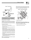
NOTE: Circuits to be moved must be protected by same
size breaker. For example, a 15 amp 120V circuit in
emergency load center will replace a 15 amp 120V
circuit in main panel.
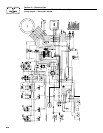
10b. In your main panel, remove the black (hot) wire from
a circuit breaker that protects a circuit you want to
have powered in the event of a power failure. Wire
nut the black wire to the matching circuit lead wire
from the emergency circuit breaker from load center
in the transfer switch. (All circuit wires are color
coded and labeled for easy identification). Repeat
this process with remaining circuits to be powered
by the generator. White wires (neutral) in your main
distribution panel should remain connected to
neutral bar. It is not necessary to move them. The
emergency load center in the transfer switch
supplies the following circuits: (5) 15A/120V, (3)
20A/120V, (1) 20A/240V and (1) 30A/240V.
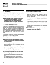
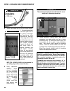
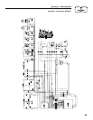
11. Install the 70 Amp double pole circuit breaker that
you have purchased into main electrical distribution
panel. This circuit breaker must be compatible with
your main electrical distribution panel. It may be
necessary to reposition remaining circuit breakers
or remove circuit breakers that have been
disconnected to accommodate the insertion of the
70 Amp double pole circuit breaker. Connect white
wire to the main distribution panel neutral bar.
Connect solid green wire to main electrical panel
ground bar. Connect the black and red wires to the
70 Amp double pole circuit breaker. Replace
electrical distribution panel cover.
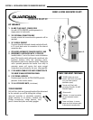
YOUR GUARDIAN
®
GENERATOR READY KIT
IS NOW INSTALLED!
Install 70 AMP Circuit Breaker
11
70
70
UL approved wire nuts are included with installation kit.
Connection of Emergency Circuits
10b
Connection of Emergency Circuits
10a
23
SECTION 5 - INSTALLATION GUIDE FOR GENERATOR READY KIT