


Generac
®
Power Systems, Inc. 31
2.6.3.1 Generator Coversion to
120 Volts Only — Dual Circuits
NOTE:
Conversion of a QUIETPACT™ generator from
"120/240 volt dual voltage" to "120 volts only -
dual circuits" (or vice-versa) requires rerouting
wires within the unit enclosure. It is recommend-
ed that this conversion be performed by a Generac
Authorized Service Dealer.
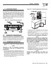
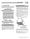
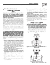
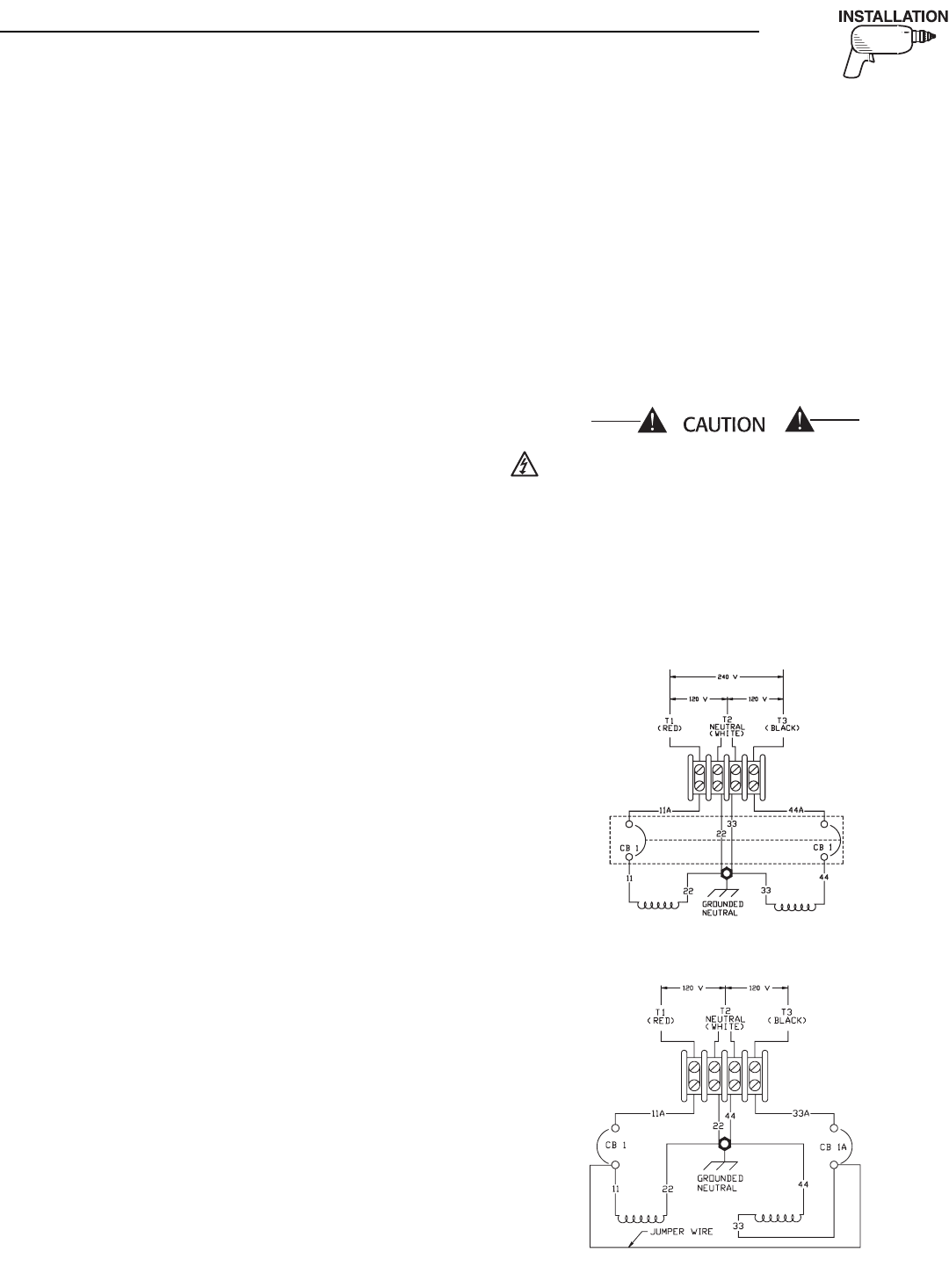
Figure 2.16 shows the stator power winding connec-
tions for 120 volts only - dual circuits. Two stator
power windings are used, with each winding capable
of supplying half of the unit's rated wattage/amperage
capacity. The circuit from each winding is protected
against overload by a line breaker (CB1 and CB1A).
Line breakers CB1 and CB1A have a trip rating of 35
amps.
To convert from "120/240 volt dual voltage" to "120
volts only - dual circuits", disconnect battery power
from the generator and reverse stator lead wires 33
and 44 as follows:
NOTE:
It is necessary to feed stator lead wires 33 and 44
through grommets on the electrical enclosure and
engine control box in order to perform the rerout-
ing outlined below. The front and top unit enclo-
sure panels, as well as the user control panel,
must be removed to perform this. After re-routing,
wires should be properly tied down to prevent
chafing or contact with moving internal compo-
nents
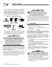
1. Remove stator lead wire 33, as shown in Figure
2.15, from the ground stud adjacent to the four-
position terminal block. Reroute stator lead 44
from the line side terminal of CB1 (renamed as
CB1A in Figure 2.16) to the ground stud location
previously occcupied by stator lead wire 33.
2. Move smaller gauge (#18 AWG) wire labeled #44
(not shown), from the top of CB1A to the top of
CB1. Renumber this wire #11.
3. Reroute stator lead wire 33, removed in step 1,
to the line side terminal on CB1A.
4. Renumber ground wire "33", located between the
four-position terminal block and ground in
Figure 2.15, as ground wire "44", as shown in
Figure 2.16.
5. Renumber wire "44A" from Figure 2.15 as wire
"33A" in Figure 2.16.
6. Connect a 12 AWG jumper wire between line
breakers CB1 and CB1A, as shown in Figure
2.16.
7. Remove the "tie bar" between the two-line break-
er switch handles.
When connecting vehicle load leads, the following
rules apply:
• Connect 120-volt, single-phase, 60-Hertz, AC elec-
trical loads, requiring up to the trip rating of cir-
cuit breaker CB1, across AC output leads T1 (red)
and T2 (white).
• Connect 120-volt, single-phase, 60-Hertz, AC elec-
trical loads, requiring up to the trip rating of cir-
cuit breaker CB1A, across AC output leads T3
(black) and T2 (white).
• Try to keep the load balanced between the two cir-
cuit breakers and the stator windings.
• The neutral line (T2, white) on all units is a
grounded neutral.
Do NOT connect electrical loads in excess of any
circuit breaker rating, or problems will develop
with circuit breaker tripping, which causes a loss
of AC output. Also, do NOT exceed the genera-
tor's rated wattage capacity. Add the watts or
amps of all lighting, appliance, tool, and motor
loads the generator will operate at one time.
This total should be less than the unit's rated
wattage/amperage capacity.
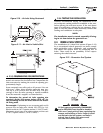
Figure 2.15 – Connections for 120/240 Dual
Voltage
Figure 2.16 – Connections for 120 Volts Only —
Dual Circuits
▼
Section 2 – Installation
QUIETPACT™ 75D Recreational Vehicle Generator