


30 Generac
®
Power Systems, Inc.
• Use exhaust system parts recommended by
Generac. Using unapproved exhaust mufflers and
exhaust system parts is the responsibility of the
person(s) installing such unauthorized parts.
• Do not terminate the exhaust system under any
opening, window, or vent that can be opened or is
not permanently sealed from the vehicle interior.
• Exhaust piping must be large enough to prevent
excessive back pressure on the generator engine.
• Never tee the generator engine exhaust pipe into
the vehicle engine exhaust piping. This causes
excessive back pressure on the generator engine.
Also, water from one engine can damage the other
engine.
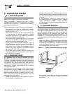
• Plan exhaust system installation carefully. Comply
with all applicable codes, standards, and regula-
tions.
2.6 ELECTRICAL CONNECTIONS
Be sure to read Section 1.6.
The following general rules apply to electrical con-
nections in a recreational vehicle:
• Qualified electricians who are familiar with applic-
able codes, standards, and regulations should
install electrical wiring.
• The wiring should comply with codes, standards,
and regulations. The National Electrical Code
(NFPA 70), and state and local codes apply.
• Switches and circuit breakers should be of a type
approved for use in recreational vehicles and must
be mounted and installed to prevent damage from
road shock.
• Wiring must be of adequate size, have approved
insulative qualities, and be properly supported.
• Conduit and wire openings into the generator com-
partment (if used) must be vapor-sealed to prevent
entry of flammable, explosive, or poisonous gases
into the vehicle.
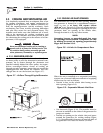
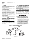
2.6.1 ELECTRICAL JUNCTION BOX
Install an approved, square electrical junction box
with a blank cover on the interior or exterior wall of
the area planed for installation of the generator (NOT
on the generator). Route the generator's AC output
leads into this junction box through approved flexible
conduit. This is the point of first termination for gen-
erator AC output leads.
2.6.2 WIRING
• Wiring should be of stranded copper to reduce the
chance that vibration may cause breakage.
• Wire gauge size should be large enough to handle
at least 115 percent of the installed generator's
rated maximum current.
• If neutral conductors are used, they must be the
same size as other leg wires.
• Route power supply conductors from generator AC
output leads T1 (red), T2 (white), T3 (black), and
the green ground wire through approved flexible
conduit to the electrical junction box on the com-
partment wall.
If a flexible metal conduit is used between the gen-
erator and the compartment junction box, the con-
duit end that terminates at the compartment junc-
tion box must be vapor-sealed. Flexible metal con-
duit is NOT vapor-tight along its entire length.
• From the junction box, route power supply wires
through approved conduit to either (a) double-
pole, double-throw transfer switch, or (b)
approved isolation receptacle. Connecting to a
transfer switch or isolation receptacle must pre-
vent vehicle electrical circuits from being connect-
ed to two different power supplies at the same time
(such as, generator and dockside power).
• Conductors must be rated 221° F (105° C) or must
be of a larger conductor size.
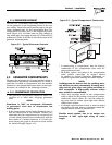
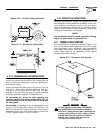
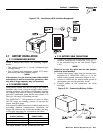
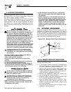
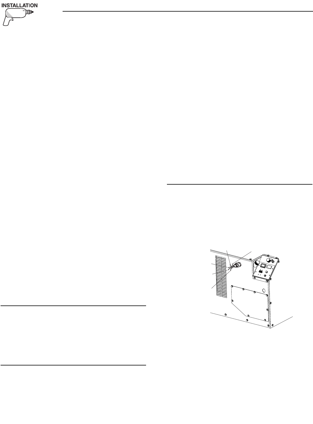
2.6.3 GENERATOR AC CONNECTIONS
Generator AC output leads T1 (red), T2 (white), and
T3 (black) come out of the generator, as shown in
Figure 2.14. Leads T1 (red) and T3 (black) are “hot,”
while T2 (white) is the grounded neutral lead. There
is also a green lead that connects to ground in the
junction box of the recreational vehicle.
Figure 2.14 – Generator AC Output Leads
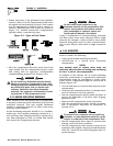
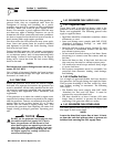
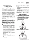
QUIETPACT ™ generators use a four-position termi-
nal block to connect between stator power leads and
vehicle load leads. This terminal block is accessible
by removing the access panel, shown in Figure 2.14.
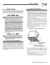
Units are shipped from the factory connected for
dual-voltage (120/240 volts AC) output (See Figure
2.15). The stator power windings are connected in
series. Lead 11/11A connects to T1 (Red), lead
44/44A connects to T3 (Black), while leads 22 and 33
are grounded and connect to T2 NEUTRAL (White). A
"tie bar" connects the two switch handles on line
breaker CB1.
T2 Neutral (White)
T1 (Red)
T3 (Black)
T2 Neutral
(White)
Ground
(Green)
◆
◆
◆
Section 2 – Installation
QUIETPACT™ 75D Recreational Vehicle Generator