GB - 28
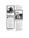
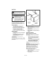
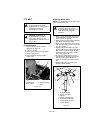
Push the mower lift pedal forward
between cutting height number 4 and
number 5 to align the holes in the deck
lift shaft and the deck lift cover. Insert the
cutting height pin in the holes on the side
of the deck lift cover so it passes all the
way through the deck lift cover and
shaft.
IMPORTANT: The mower lift arms are not
locked unless the cutting height adjustment
pin passes all the way through both the deck
lift cover and shaft.
NOTE: Support the mower deck on blocks or
jack stands before disconnecting link chains
from mower lift arms to prevent the deck from
falling.
3. Remove link chains from mower lift
arms. Note hole location on mower lift
arms for replacement.
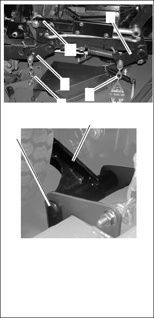
4. Remove the mower mounting pins
connecting the mower mounting arms to
the deck.
5. Slide mower deck out from under unit.
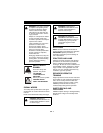
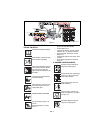
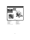
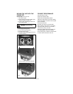
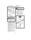
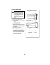
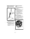
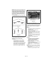
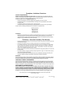
Installing the Mower Deck (Figure 22)
1. Slide mower deck under unit.
2. Connect mower mounting arms to deck
with mower mounting pins.
3. Install link chains on the mower lift arms
in the same holes they were removed
from.
4. Install PTO mower belt (See Replacing
Mower Belts on page 26).
5. Level mower deck (See Leveling the
Mower Deck on page 28).
Leveling the Mower Deck
These adjustments should be made on a
level surface with the tires inflated to the
correct air pressure.
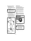
Check Blade Level and Pitch
1. Raise mower deck to a 3 in. (7.62 cm)
cutting height.
2. Shut off engine. Engage parking brake.
Remove the ignition key.
NOTE: Place blocks under the bottom edge
of the deck, not under the reinforcement bar
welded along deck face.
3. Place blocks at each corner of the deck
to support the weight of the deck.
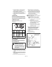
4. Turn the blades so the blade ends point
left to right across the width of the deck.
5. Measure the distance between the
ground and cutting edge of the blade on
the left blade (Left position in Figure 23)
and on the right blade (Right position in
Figure 23). Distances should be within
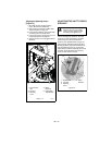
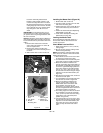
3/16 in. (4.7 mm). If they are not, raise
the low side of the deck using the height
adjusters on the deck lift brackets (see
Figure 24).
6. After deck is level side to side, check the
deck front to back pitch.
7. Turn the blades so the blade ends point
front to back as shown in Figure 23.
8. Measure the distance between the
ground and the cutting edge of the
middle blade at the front of the deck
(Front position in Figure 23) and
between the ground the cutting edge of
the left and right blades at the rear of the
deck (Rear position in Figure 23).
9. The cutting edge at the front of the deck
(Front position in Figure 23) should be
1/8 in. (3.18 mm) lower than the cutting
edges at the rear of the deck (Rear
position in Figure 23).
10. If measurements are out of range, raise
the low side of the deck using the height
adjusters on the deck lift brackets (see
Figure 24). Be sure to raise the deck
evenly to keep the deck level side to
side.
Figure 22
1. Mower Lift
Arm
2. Link Chain
3. Mower
Mounting Arm
4. Mower
Mounting Pin
5. Mower Lift
Arms Locked
3
OF3765
4
2
2
1
1
5