


27
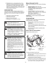
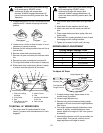
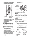
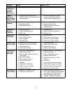
Clutch Shaft Belt Replacement
1. Remove transaxle belt (see procedure above).
2. Remove clutch shaft idler spring from frame.
3. Remove clutch shaft belt from engine sheave.
4. Remove clutch shaft belt from clutch sheave.
5. Install new belt onto clutch sheave, then engine
sheave. Check for belt alignment and clearance.
6. Connect clutch shaft idler spring to bolt.
7. Reinstall transaxle belt.
ADJUSTMENTS
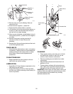
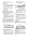
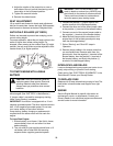
Neutral Adjustment (Speed Control Lever)
1. Stop the engine. Remove the ignition key. Push
the PTO knob into the “OFF” position.
2. Place jack(s) under rear transaxles only. If jack(s)
are not available, place support blocks under both
transaxles at the rear of the unit.
3. Raise the rear drive wheels off the floor. Remove
side shrouds. Set aside.
4. Start the engine and run it at part throttle.
5. Loosen the two lock nuts holding the Speed
Control Arm.
6. Rotate Flange Bushing until the wheel stops
rotating.
7. Lock the Speed Control Arm in place by
tightening the two lock nuts.
8. Repeat procedure for other side of unit.
9. Reinstall side shrouds.
ADJUSTING THE UNIT TO TRACK
STRAIGHT
The primary reason the unit may not track straight is
incorrect or unbalanced tire air pressure. First, check
and adjust tire pressure. Increase pressure on the side
the unit tracks toward. DO NOT exceed maximum
recommended tire pressure. See
Specifications
.
If adjusting tire air pressure does not the solve tracking
problem the steering control lever travel may need to
be adjusted.
To check steering control levers:
With the engine off, push the steering control levers to
their full forward position. If one lever travels farther
than the other, they need to be adjusted.
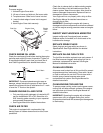
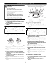
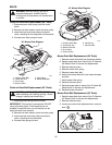
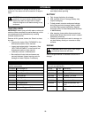
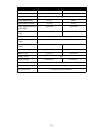
To adjust:
1. Remove side shrouds. Set aside.
2. Loosen bolts which attach the eccentric to the
seat support. Do not remove the bolts.
3. Rotate eccentric to adjust the travel of the speed
control arm. The thicker portion of the eccentric
shortens the distance the steering control lever
will travel forward. The thinner portion of the
eccentric lengthens the distance the steering
control lever will travel forward.
CAUTION:
PREVENT personal injury!
ALWAYS MAKE CERTAIN that jack(s) or
blocks used are stable, strong and will
support the weight of the unit.
OE0840
2
1
3
4
5
6
1. Transaxle Belt
2. Clutch Shaft Idler
Spring
3. Clutch Shaft Belt
4. Engine Sheave
5. Clutch Sheave
6. Clutch Idler
Speed Control Arm
Locknuts and Bolts
Locknuts and Bolts
Flange Bushing
OE0082
Eccentric
OE0850
Shorter Travel
Longer Travel
1. Eccentric
2. Bolt
3. Speed Control Arm
1
2
3
1
2
3