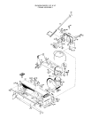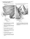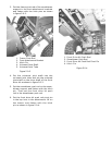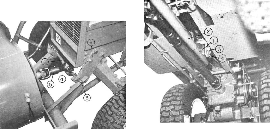
3. Put the frame pivot rod of the snowblower
support in the front attachment brackets
and fasten with the hitch pins as shown
in figure 5.0-3.
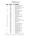
1. Frame Pivot Rod
2. Front Attachment Bracket
3. Hitch Pin
4. Universal Joint Shaft
5. Universal Joint Tube
Figure 5.0-3
4. Put the universal joint shaft into the
universal joint tube and put the universal
joint shaft on the drive shaft of the front
drive kit as shown in figure 5.0-3.
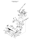
5. Put the snowblower push rod on the snow-
blower support and fasten with the hitch
pin. Then put the front drive kit push
rod in the snowblower push rod.
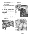
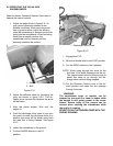
6. Put the front drive kit push rod pivot pin
in the top hole in the attachment lift on
the tractor and fasten with the hitch
pin as shown in figure 5.0-4.
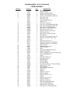
1. Front Drive Kit Push Rod
2. Snowblower Push Rod
3. Front Drive Kit Push Rod Pivot Pin
4. Hitch Pin
Figure 5.0-4


