


18 308–530
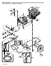
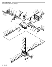
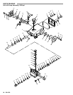
GEAR REDUCER SERVICE (Models 2040 & 2540)
WARNING
To
reduce the risk of serious bodily injury
, including fluid injection, splashing in the eyes or on the skin
or injury from
moving
parts, always follow the
Pressure Relief Procedure W
arning
on page 2 before proceeding.
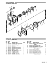
Replacing the Gasket (9)
NOTE: To maintain a good seal, the gasket must be
replaced whenever the gear reducer is
disassembled.
1. Remove the four bolts, lockwashers and washers.
Pull the pump and gear reducer assembly of f the
engine.
2. Drain the gear reducer oil by placing a container
under it and removing the drain plug with a 22 mm
wrench.
Replace the o–ring (15) if damaged.
3. Remove the nine screws with a 6 mm wrench and
pull
the gear case of
f the gear cover
.
4. Remove
the old gasket (9). Clean the gear cover and
case surface. Lightly coat the new gasket with
grease
and install it in on the gear case.
5. Follow
steps 5 through 7 under
Assembling the Gear
Reducer
if this is all the service required.
Replacing the Oil Seals (21)
1. Follow steps 1 through 3 under Replacing the
Gasket.
2. Loosen
the setscrew
,
using a 4 mm wrench, and pull
the gear (4) of
f the pump with a gear puller
.
3. Using
a 6 mm wrench, remove the four screws. Keep
them separate from the other nine screws removed
previously.
4. Remove
the four oil seals (21) and replace them.
5. Follow
steps 2 through 7 under
Assembling the Gear
Reducer
if this is all the service required.
Replacing the O–Ring (1)
1. Follow the instructions under Replacing the Gasket
and
Replacing the Oil Seals to disassemble the gear
reducer.
2. Pull the gear cover of f the pump and replace the
o–ring (1).
3. Follow instructions under Assembling the Gear
Reducer
if this is all the service required.
Replacing the Oil Seal (14)
NOTE:
The oil seal MUST be replaced if removed.
1.
Follow steps 1 and 3 under Replacing the Gasket.
2. Remove
the snap ring
(6) from the gear case, using a
snap
ring pliers. Pull the gear and bearing.
3. Push the seal from the inside to the outside of the
gear case by placing screwdriver against the seal
and
lightly tapping it with hammer
.
4. Wipe
the inner surface of
the case clean, then lightly
coat it with grease. Place the oil seal into the gear
case.
Use a socket, placed against the surface of the
seal, to push the seal into the case until its top
surface
is past the ridge in the bore.
5.
Place the
gear and bearing back into the gear case
and
install the snap ring (6).
6. Follow
steps 4 through 7 under
Assembling the Gear
Reducer
if this is all the service required.
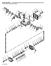
Assembling the Gear Reducer
1. Grease
the o–ring and make sure it’
s properly placed
on
the gear cover
.
2. Place
the four oil seals and
screws in the gear cover
.
Place
the o–ring on the screw to hold it
in the cover
.
3. Apply low strength Loctiter (blue) on the screw
threads,
align the
screws with the holes in the pump,
and
tighten the screws oppositely and evenly
.
4. Grease
the pump shaft. Align the gear
’
s slot with the
key on the pump shaft and slide the gear onto the
shaft,
up to the pump’
s shoulder
. Apply low strength
Loctiter on the setscrew threads and tighten the
setscrew
to lock the gear on the shaft.
5. Make
sure the gasket is
in place (refer to step 4 under
Replacing
the Gasket). Install the gear cover on the
case, aligning the holes, and secure it with the nine
screws
and lockwashers. T
ighten the screws
evenly
in
a crisscross pattern.
6. Grease
the engine shaft. Align the gear
’
s slot with the
key on the engine shaft and slide the gear reducer
onto
the shaft, up to the engine’
s shoulder
.
7. Secure the gear reducer to the engine with the four
bolts,
lockwashers and washers.