


26 308–530
PUMP
SER
VICE (Model 1535)
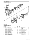
Servicing the Valves
Disassembly:
1. Remove the four (4) socket head bolts and spring
washers
from end of manifold.
2. Support the discharge manifold from the underside
and tap with a soft mallet to separate from the inlet
manifold.
3. Carefully place discharge manifold on working
surface
with valve chambers up.
4. From
the three (3) smaller diameter and shallow inlet
chambers
remove the inlet valve adapters with inner
and outer o–rings. These adapters are not held
securely
in position and may fall out as the discharge
manifold
is removed.
5. Next remove the valve seats, valves, springs and
retainers
from the inlet chambers.
6. From the three (3) larger diameter and deeper
discharge chambers remove the discharge valve
spacers
with o–rings. These
brass spacers generally
remain
with the discharge manifold as it is removed.
A reverse pliers fitted into the center bore and
hooked onto the side ports of the spacer will assist
the
removal.
7. Next remove the valve seats, valves, springs and
retainers
from the discharge chambers.
NOTE: The inlet and discharge use the same
retainers,
springs, valve seats and valves. The
o–rings and valve spacers/adapters are
different. Keep parts in order as they are
removed.
Reassembly:
(DISCHARGE)
1. With
crankcase side of discharge manifold facing
up,
insert the springs into the retainers over the plastic
center
guide.
2. Place valve spring retainers in deeper valve
chambers. They will rest on the machined ridge in
each
chamber
.
3. Examine
the valves for wear or pitting and replace if
necessary. Install valves over the springs with
recessed
(dish) side down.
4. Examine valve seat o–rings for wear and replace.
Lubricate and place o–rings on lip of retainers.
Carefully square o–rings in valve chamber to avoid
cutting
o–ring when valve seat is installed.
5. Examine valve seats for pitting, scale or ridges and
replace
if necessary
. Install valve
seat with grooved
side
down, so o–ring fits snugly into groove on seat.
6. Examine
both o–rings
on the discharge valve spacer
and replace if necessary . Lubricate o–rings and fit
into
grooves on outside of spacer
.
7. Lubricate spacer and carefully press into valve
chambers
with small diameter side down until spacer
snaps
tightly into position.
Reassembly: (INLET)
1. Place valve spring retainers into the shallow valve
chambers. They will rest on the machined ridge in
each
chamber
.
2. Insert
valve springs into retainers
over plastic center
guide.
3. Inspect the valves for wear , ridges or pitting and
replace if necessary. Insert valves over the springs
with
recessed (dish) side down.
4. Examine valve seat o–rings for wear and replace.
Lubricate and place o–rings on lip of retainers.
Carefully square o–rings in valve chamber to avoid
cutting
o–ring when valve seat is installed.
5. Examine valve seats for pitting, scale or ridges and
replace
if necessary
. Install valve
seat with grooved
side
down, so o–ring fits snugly into groove on seat.
6. Examine the adapter inner o–rings and replace if
worn. Lubricate and install o–rings into inlet valve
adapters.
7. Examine the adapter outer o–rings and replace if
worn. Lubricate and install o–rings onto inlet valve
adapters.
8. Lubricate
inlet valve adapter and press into
chamber
.
Carefully
square inlet valve adapter into chamber to
avoid
cutting or extruding o–ring.
9. Replace discharge manifold over plunger ends
matching discharge valve spacers with inlet
chambers and press into position. T ap with a soft
mallet
until completely seated in chambers.
10. Replace
all four (4) washers and socket head bolts.
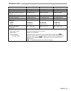
Hand tighten each. Then torque per chart.
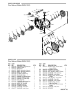
Servicing the Seals
Disassembly:
1. With discharge manifold removed from the pump
remove the two (2) socket head bolts and spring
washers
from end of inlet manifold.
2.
Rotate crankshaft to loosen inlet manifold.
3. Support
inlet manifold from
underside and tap with a
soft
mallet to separate manifold from crankcase.