


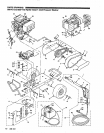
PUMP
SERVICE
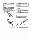
Servicing the Valves
1.
Remove the hex valve plug.
2.
Examine the O-ring under the plug for cuts or
distortion and replace
if
wom. Lubricate new O-ring
before installing.
3.
Grasp valve retainer by tab at the top with pliers and
remove from valve chamber. Valve parts usually
separate during removal.
Note:
A
special
tool
will be needed
to
remove the
seat from the manifold.
A
reverse pliers or a
of seat Inserted under the edge
of
the seat, will
standard vise grip and a
1/4”
x
3”
bolt
to
fit
I.D.
pry the valve seat out easily.
4.
Examine all valve parts for wear and replace with
preassembled valve assembly in sefvice kit
containing retainer, spring, valve, valve seat,
O-ring, and back-up ring.
5.
Grasp new valve assembly by tab
at
top with pliers,
immerse in oil and push into valve chamber. Be
certain valve assembly is square in valve chamber.
6.
ApplyLoctite242tovakreplug,threadintomanifold
port and torque per chart.
Note:
Corrosion Resistant models require the coil
spring installed in the Valve Plug.
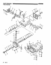
Servicing the Pumping Section
Dlsassembly:
1.
Remove the four
(4)
hexnuts ortwo
(2)
boltsfromthe
manifold (varies with model).
2.
Rotate crankshaft by hand
to
start separation of
manifold from crankcase. Support the underside of
the manifold and tap lightly with a mallet
to
remove
the manifold assembly.
CAUTION
plungers when removing
to
avoid damage
to
Keep manifold properly aligned with ceramic
either plungers or seals.
3.
4.
5.
6.
18
wicks.
Remove oil pan and slide out seal retainer with
Using a wrench, loosen the plunger retainer. Grasp
ceramic plunger and push toward crankcase until
plunger retainer pops out.
Remove plunger retainer with copper gasket,
back-up Ring and O-ring.
Remove plunger from plunger rod.
308-531
Reassembly:
1.
Carefully examine each ceramic plunger for scoring
or cracks, replace ifwom and slip onto plunger rod.
Note:
Ceramic plunger can only be installed one
direction (front
to
back).
Do
not force onto rod.
2.
Examine plunger retainer and stud and replace if
worn.
Note:
Thread stud into plunger retainer.
3.
Examine O-ring. back-up ring and gasket on
plunger retainer and replace ifwom or cut. Lubricate
O-ring for ease of installation
and
to
avoid
damaging O-rings.
Note:
First install gasket, then back-up ring and
4.
5.
6.
7.
8.
9.
O-ring.
Thread plunger retainer and
stud
assembly into
plunger rod. Exercise caution not
to
over torque.
seal retainer and slip retainer over ceramic plunger.
Saturate new oil wick by soaking in oil, place in
Replace
oil
pan.
Tum shaft by hand
to
line up plungers
so
end
plungers are parallel.
Carefully slip manifold onto plungers, keeping
manifold level, and tap with mallet
to
bring manifold
flush with crankcase.
chart.
Replace washers and nuts
or
bolts and torque per
Servicing the Seals and V-Packings
Disassembly:
1.
2.
3.
4.
5.
6.
Remove the manifold as described.
With crankcase side of manifold facing up, unscrew
the seal case from the manifold using
a
special key
wrench.
Remove O-ring from seal case.
seal case. Seals are generally removed easily
Remove snap ring and low pressure seal from the
without any
tools.
Hlgh
Pressure Seal Models:
The high pressure
without any
tools.
If
extremely worn a reverse pliers
seal is generally easily removed from the manifold
may be used.
V-Packlng
Models:
The female adapter, two
v-packlngs and male adapter are easily removed
from manifold without
tools.
If extremely wom
a
reverse pliers may be used.