


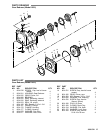
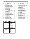

27308–530
4. With crankcase side of manifold down remove
hi–pressure
seals using a reverse pliers.
5. Invert manifold so crankcase side is up and with
reverse
pliers remove low pressure seals.
Reassembly:
1. Examine low pressure seal for seal wear or spring
failure
and replace if necessary
.
With crankcase side
of inlet manifold up, lubricate seal and press into
valve chamber with garter spring down. Carefully
square
seal into position.
2. Examine hi–pressure seal for wear and replace if
necessary.
Invert inlet manifold
with crankcase side
down, lubricate seal and press into chamber with
v–side
up. Carefully square into position.
3. Rotate shaft so the two (2) outside plungers are
extended
and lined–up.
4. Lubricate plungers and discharge valve adapter
o–rings.
5. Carefully line–up and join the inlet and discharge
manifolds
by pressing the protruding discharge valve
adapters
into the inlet manifold seal chambers.
6. Replace
all four (4) discharge
manifold socket head
bolts
and washers and hand tighten.
7. Then
carefully
slip manifold assembly onto plungers
and
tap with soft mallet until flush with crankcase.
8. Replace
the two (2)
inlet manifold socket head bolts
and washers and hand tighten. Then torque per
chart.
9. Then torque the four (4) discharge manifold socket
head
bolts per chart.
Servicing the Plungers
Disassembly:
1. Remove
discharge and inlet manifold as described.
2. Using a wrench loosen plunger retainers
approximately three (3) to four (4) turns.
3. Grasp
ceramic
plunger and push towards crankcase
until
plunger retainers with stud pop out.
4.
Remove plunger retainer and copper gasket.
5.
Remove ceramic plunger from plunger rod.
6.
Remove barrier slinger from plunger rod.
Reassembly:
1. Replace barrier slinger if necessary and position
onto
plunger rod.
2. Carefully examine ceramic plunger for scoring or
cracks
and replace if worn. Slip onto rod.
NOTE: Ceramic plunger can only be installed one
direction
(front
to back). Do not force onto rod.
3. Examine o–ring and back–up ring on plunger
retainer and replace if worn or cut. Lubricate o–ring
for ease of installation and to avoid damage to
o–rings.
NOTE: First install NEW copper gaskets on plunger
retainers,
then back–up rings and o–rings.
4. Install short threaded end of stud into plunger
retainer.
5. Thread plunger retainer and stud assembly into
plunger
rod and torque per chart. (Long threaded end
of
stud into plunger rod.)
NOTE: Exercise
caution not to over torque the plunger
retainer.
6. Rotate shaft so the two (2) outside plungers are
extended
and lined–up. Then lubricate plungers.
7. Replace
all four (4) discharge
manifold socket head
bolts
and washers and hand tighten.
8. Then
carefully
slip manifold assembly onto plungers
and
tap with soft mallet until flush with crankcase.
9. Replace
the two (2)
inlet manifold socket head bolts
and washers and hand tighten. Then torque per
chart.
10. Then torque the four (4) discharge manifold socket
head bolts per chart.
Servicing Crankcase Section
1. While
inlet manifold, plungers and seal retainers are
removed,
examine crankcase seals for wear
.
2.
Check oil level and for evidence of water in oil.
3. Rotate
crankshaft by hand to feel for smooth
bearing
movement.
4. Examine crankshaft oil seal externally for drying,
cracking
or leaking.
5. Consult factory or your local distributor if crankcase
service is required.
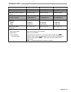
T
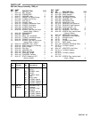
orque Chart
Pump Part
Thread T
ool Size
Torque
Plunger Retainer
M5 1
1 mm hex
80 in. lbs.
Inlet Manifold
Bolts
M10
8 mm a
llen 13
2 i
n
. l
bs.
Discharge
Manifold Bolts
M10
8 mm a
llen
180 in. lbs.