


5
308-534ą5
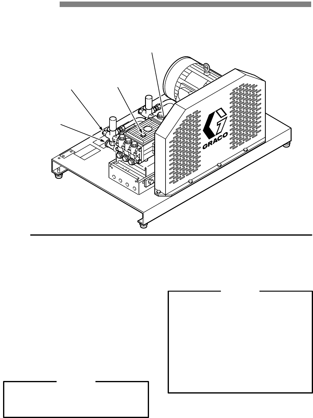
INSTALLATION
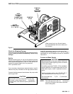
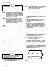
Figure
1
PUMP DIP
-
STICK
HIGH
PRESSURE
HOSE
CONNECTION
2 x 1/2” NPT(f)
WATER
CONNECTION
2 x 1” NPT(f)
PUMP OIL
LEVEL
INDICATOR
WINDOW
W
ater supply tank, gun & wand assem
-
bly
, hose assembly and motor starter are
not included.
Check for Shipping Damage
Check
the unit for
any damage that may have occurred in
shipping.
Notify the carrier immediately if there is any
damage.
Set Up
Before
connecting the unit, be sure the electrical
service
matches
the specification in T
echnical
Data (inside back
cover)
and the voltage label
on the unit. With the unit of
f,
connect the power supply cord to a grounded,
GFCI–protected
circuit.
If
you are using a
downstream chemical injector
, install it
between
the pump unloader and the
high pressure hose.
Connect
the
high pressure hose between the pump outlet
and
the gun inlet.
CAUTION
Up to 100 ft (30 m) of high pressure hose may
be used.
Longer hoses may af fect sprayer
performance,
and chemical injector
performance,
if
used.
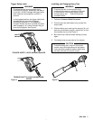
Install the appropriate spray tip on the wand. See
Installing and Changing Spray T ips. If you are using a
sandblaster kit, see its separate manual for installation
instructions.
Connect to Water Supply
CAUTION
Before attaching to the water supply, check your
local plumbing code regarding
cross–connection
to the water supply
.
A
backflow preventer P/N 801–133 is available
to
prevent backflow of contaminated water into the
fresh water supply . Install it upstream from the
pump.
Install a regulating water valve, P/N 800–258, if
inlet
water pressure is over 60 psi (4.1 bar).
Do not exceed 160 _ F (70_ C) inlet water
temperature.
NOTE: The water source for the unit
must
have a
minimum 100 gallon float valve controlled
water
holding tank.