


17
PUMP SERVICE: 4043 MODEL
PRESSURE WASHERS
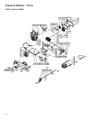
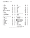
Repair kits are available. See the Parts List, page 22.
For the best results, use all parts in kits.
Follow Shutdown Procedure, page 13 to relieve system
pressure.
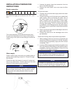
Valves
For a set of six valves, order Valve Assembly Kit
801472.
1. Remove hex plug from the manifold using a 30mm
wrench.
2. Examine o-ring under hex plug and replace if cut or
distorted.
3. Remove valve assembly from cavity. The assembly
may come apart!
4. Install new valve, o-ring and hex plug. Torque to 73.7
ft-lb (100 Nm).
Note: Retorque the plug after 5 hours operation.
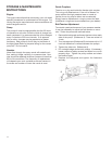
Pumping Section
1 Remove the eight capscrews and lock washers from
manifold.
2. Carefully separate manifold from the crankcase. You
may have to lightly tap the manifold with a soft mallet
to loosen it.
NOTICE
To avoid damage to plunger or seals, keep manifold
properly aligned with the ceramic plungers when
you remove it.
3. Carefully examine each plunger for any scoring or
cracking. Replace as necessary.
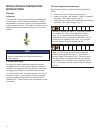
Servicing Plungers
Note: Plunger repair kit 803510 is available to replace
retainers, o-rings, washers, and backup rings for three
cylinders.
1. Loosen plunger retaining screw ve or six turns. Push
plunger toward the crankcase to separate plunger and
retaining screw.
2. Remove screw from plunger and examine o-ring,
backup ring, and copper bearing/gasket washer.
Replace these parts, if necessary.
3. Remove plunger and inger from plunger shaft. Clean,
examine and replace parts as necessary.
4. Inspect plunger shaft for oil leaks from crankcase. If
leaking is obvious, replace oil seals. Otherwise, DO NOT
remove these seals because they cannot be reused.
Oil Seal Kit 801473 is available for replacing seals.
5. Lightly grease the inger (and oil seal if it is being
replaced), and replace the plunger shaft. Then install
the plunger.
6. Lightly grease the retaining screw and outer end of the
plunger. Place washer, o-ring and backup ring around
screw and install nut through plunger. Torque to 14.7
ft-lb (20 Nm).
Note: If replacing packings, see Servicing V-Packings.
7. Lubricate outside of each plunger. Slide the manifold
on the crankcase, being careful not to damage seals.
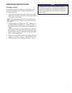
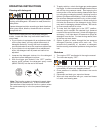
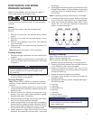
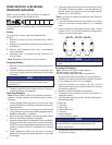
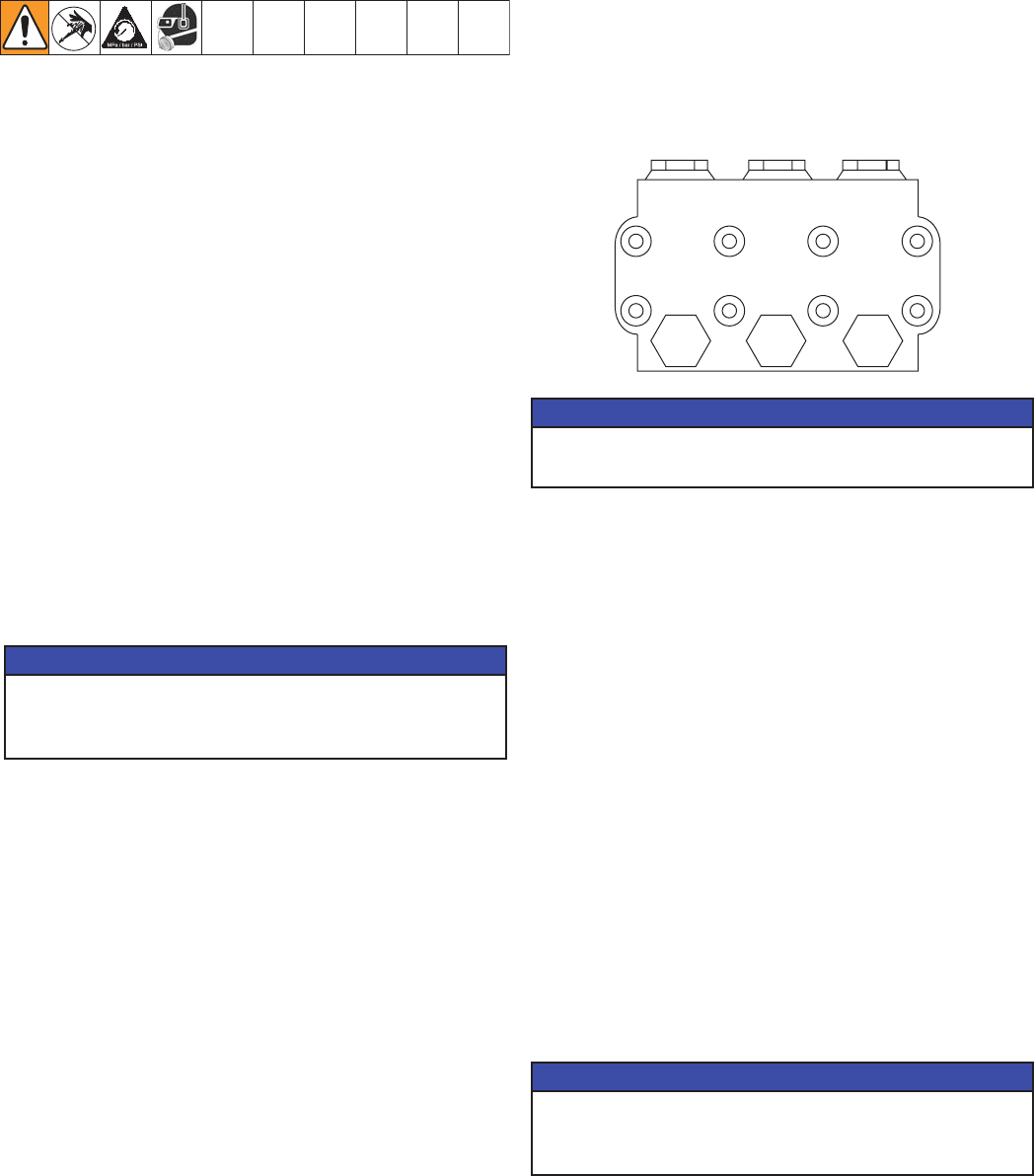
8. Install cap screws and washers nger tight. Torque
screws 22.1 ft-lb (30 Nm) following the tightening
pattern in the following gure.
NOTICE
Uneven tightening could cause the manifold to bind
or jam.
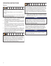
Servicing V-Packings
Note: There are two types of packing kits:
803511 contains packings only.
803512 contains packings, rings and retainers.
1. Remove manifold as described in Pumping Section.
2. Carefully pull packing retainer from manifold. Examine
o-ring. Replace o-ring if cut or damaged.
3. Remove V-packing and head ring. Pull out the
intermediate retainer ring. Remove second V-packing
and second head ring.
4. Inspect all parts and replace as necessary.
5. Thoroughly clean packing cavities and inspect for
damage or debris.
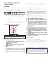
6. Lightly grease packing cavities. Replace packings in
the following order:
• head ring
• v-packing
• intermediate ring
• head ring
• v-packing
• packing retainer
• o-ring in retainer groove
NOTICE
Install the parts in the proper order and facing the
correct direction. Improperly installed parts will
cause a malfunction.
7. Reassemble manifold following procedure described
in Servicing Plungers.
51
47
83
26