


19
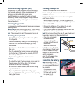
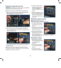
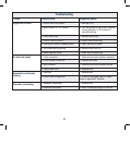
Petrol tank filter
1. Stop the engine.
2. Turn the fuel lever to the
‘off’ position.
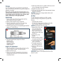
3. The petrol tank filter is
located directly under
the petrol cap (2).
This protects impurities
entering the fuel tank
during refuelling.
4. Remove the filter (Fig. N) and wash thoroughly in a solvent.
5. Re-assemble.
Tap extension fuel filter
A small fuel filter has been fitted to the inlet side of the fuel
valve (20), inside the tank. This tap extension fuel filter (12)
prevents any dirt in the fuel from entering the fuel system.
The procedure for removing this filter in order to replace or
clean it is given below.
Note: the following procedure should be performed in
a well ventilated area, with no naked flames, sparks,
or cigarettes.
Safety glasses should also be worn and engine switch (10)
set to the OFF position.
1. Completely empty the tank of fuel. Ensure the fuel tap
(20) is in the OFF position
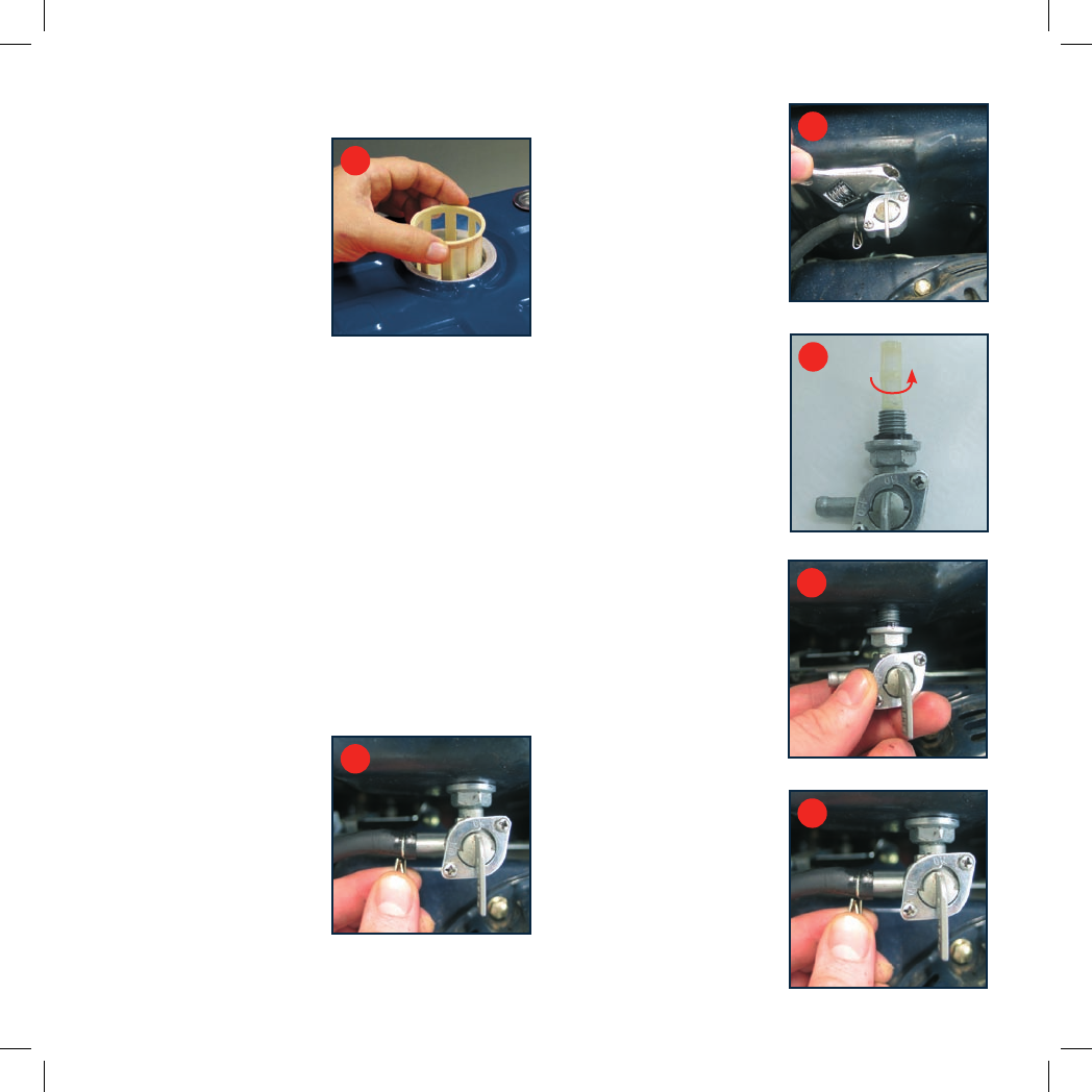
2. Compress the two wire arms
of the hose clamp on the
outlet hose at the tap (20)
and slide the clamp back
from the end of the hose
by approx. 25mm. Slide the
fuel hose off the outlet of
the tap (20) (Fig. O).
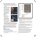
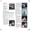
3. Loosen the lock nut locking
the tap (20) on to the tank
(Fig. P). Unscrew the tap
from the tank and withdraw
the tap from the tank. Be
careful not to lose the small
seal on the thread of the tap.
4. Unscrew the tap extension
fuel filter (12) (Fig. Q).
Note. This filter can be
cleaned in petrol to remove
any build-up of dirt on the
outside of the filter, or the
filter can be replaced. Do not
operate the generator without
this filter in place. To replace
the filter after cleaning, or
with a new filter, simply screw
the filter into the inlet side of
the tap.
5. Ensuring the small seal
is fitted to the tap thread,
screw the tap back into the
tank by a FULL 3–4 turns.
Orientate the tap so the
outlet of the tap is towards
the rear of the tank, and
the tap control is to the
right hand side of the tank.
Holding the tap firm, tighten
the lock nut, ensuring the
seal is clamped between
the lock nut and the tank
(Fig. R).
6. Refit the fuel hose to the
outlet of the tap and with the
wire arms compressed, slide
the hose clamp up onto the
connection of the hose and
the tap (Fig. S).
N
O
P
Q
R
S