


FUEL SYSTEM
FUEL REQUIREMENTS
The standby generator may be equipped with one of
the following fuel systems:
• Natural gas fuel system
• Propane vapor (PV) fuel system
The Manual Drawing Listing that is affixed to the
unit includes the “Identification Code,” which may be
used to identify the type of fuel system installed on
the unit.
Recommended fuels should have a Btu content of at
least 1,000 Btus per cubic foot for natural gas; or at
least 2,520 Btus per cubic foot for LP gas. Ask the
fuel supplier for the Btu content of the fuel.
Required fuel pressure for natural gas is 5 inches
to 14 inches water column (0.18 to 0.5 psi); and
for liquid propane, 5 inches to 14 inches of water
column (0.18 to 0.5 psi).
NOTE:
Any piping used to connect the generator to the
fuel supply should be of adequate size to ensure
the fuel pressure NEVER drops below five inches
water column for natural gas or 5 inches water
column for propane vapor for all load ranges.
NOTE:
It is the responsibility of the installer to make sure
that only the correct recommended fuel is sup-
plied to the generator fuel system. Thereafter, the
owner/operator must make certain that only the
proper fuel is supplied.
NATURAL GAS FUEL SYSTEM
Natural gas is supplied in its vapor state. In most
cases, the gas distribution company provides piping
from the main gas distribution line to the standby
generator site. The following information applies to
natural gas fuel systems.
• Gas pressure in a building is usually regulated by
national, state and local codes.
• To reduce gas pressure to a safe level before
the gas enters a building, a primary regulator is
needed. The natural gas supplier may or may not
supply such a regulator.
• It is the responsibility of the gas supplier to make
sure sufficient gas pressure is available to operate
the primary regulator.
• Gas pressure at the inlet to the fuel shutoff sole-
noid should not exceed approximately 14 inches
water column (0.5 psi). Optimum pressure at the
fuel shutoff solenoid is 11 inches water column
(0.4 psi).
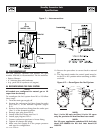
PROPANE VAPOR WITHDRAWAL FUEL SYSTEM
This type of system utilizes the vapors formed above
the liquid fuel in the supply tank. Approximately 10
to 20 percent of the tank capacity is needed for fuel
expansion from the liquid to the vapor state. The
vapor withdrawal system is generally best suited for
smaller engines that require less fuel. The installer
should be aware of the following:
• The natural gas and LP gas systems are similar.
However, the natural gas system delivers gas at a
pressure of approximately five inches water col-
umn to the carburetor.
• When ambient temperatures are low and engine
fuel consumption is high, the vapor withdrawal
system may not function efficiently.
• Ambient temperatures around the supply tank
must be high enough to sustain adequate vaporiza-
tion, or the system will not deliver the needed fuel
volume.
• In addition to the cooling effects of ambient air, the
vaporization process itself provides an additional
cooling effect.
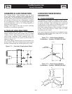
LP FUEL SYSTEM
LP is supplied as a liquid in pressure tanks. It is
usually made up of propane, butane, or a mixture of
the two gases. Propane tends to vaporize readily even
at temperatures as low as -20° F (-29° C). However,
butane reverts to its liquid state when temperatures
drop below 32° F (0° C).
LP in a liquid withdrawal system must be converted
to its gaseous state before it is introduced into the
engine carburetor. A vaporizer-converter is generally
used to accomplish this. In such a converter, heated
engine coolant is ported through the converter to
provide the necessary heat for conversion of the fuel
from a liquid to a gaseous state.
5-1
Standby Generator Sets
Fuel Systems
FuelSys001 Rev. 0 08/05