


14 Generac
®
Power Systems, Inc.
3.2.2 FAULT INDICATOR LED
This LED goes ON when one or more of the following
engine faults occurs and when engine shuts down.
• Low Oil Pressure
• Overcrank
• Low Battery
• Overspeed/RPM Sensor Loss
• High Coolant Temperature/Low Coolant Level
See Section 1.7 for further explanation of engine pro-
tection functions.
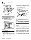
3.2.3 15 AMP FUSE
This fuse protects the control console’s DC control
circuit against electrical overload. If the fuse has
melted open because of an overload, engine cranking
and startup cannot occur. If the fuse needs to be
replaced, use only an identical 15-amp replacement
fuse. (Type AGC)
3.2.4 4 AMP INLINE FUSE
This fuse protects the battery charger against electri-
cal overload. If the fuse needs to be replaced, use only
an identical 4 amp replacement fuse (type AG).
NOTE:
This fuse will not remove the + battery input
power from the PCB when it opens. This means
the exercise timer will not be reset.
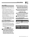
3.2.5 SET EXERCISE TIME SWITCH
This switch allows programming the generator to
start and exercise automatically. “See Weekly
Exercise Cycle.”
3.2.6 SYSTEM READY LED
The System Ready LED (green) has two main pro-
poses. First, the LED will be ON when the
AUTO/OFF/MANUAL switch is in the AUTO position,
utility is present, and there are no system alarms.
This ON state indicates the system is fully ready for
automatic operation.
The system ready LED will be OFF when the switch
is in the manual or OFF positions.
The system ready LED is also used to indicate the
presence of utility sensing at the PCB when the switch
is either in the AUTO or MANUAL modes. The LED
will flash at the rate of 1/2 second on, 1/2 second off
if the utility sensing level is below the transfer back
threshold.
This secondary function is only available with dip
switch two in the OFF position (standard ATS appli-
cation).
3.3 MANUAL TRANSFER AND
START-UP
To transfer electrical loads to the Standby (EMER-
GENCY) power source side and start the engine man-
ually, refer to the Owner’s Manual of the particular
transfer switch.
3.4 ENGINE GOVERNOR
ADJUSTMENTS
Engine speed governing is also controlled by the
engine control board. Connector J2 on the engine
control board interfaces with a governor driver mod-
ule and the Bosch throttle body. The engine governor
has been set by the factory during final testing of the
generator and, in most cases, should not be adjusted.
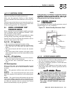
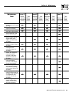
If, however, adjustments are necessary, or a new
engine control board is installed in the generator, the
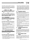
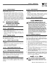
following procedure should be followed (Figure 3.2):
1. Set all three potentiometers (pots) fully counter-
clockwise.
2. Under no load condition, increase the GAIN pot
as much as possible without causeing instability.
3. Apply 1/4, 1/2, 3/4 and full load to the unit.
Decrease the GAIN pot if there is instability at any
load point.
4. Under full load condition, increase the stability
pot until the unit returns to 60 Hertz (or 50 Hertz
in 50 Hertz applications).
Figure 3.2 — Engine Governor Adjustment
PCB# 0E4906 REV.
R4
9
D17
J2
C2
C
2
6
U7
C
2
7
R44
Q2
D1
9
C30
RL1
2
L
3
LE
D
1
C4
R
2
5
C9
C
2
1
D
1
0
J1
R4
8
R1
U1
RL2
1
2
3
4
UNUSED
GTS/ATS
50/60 HZ
POSITION 1
50/60 HZ
ON = 50 HZ
OFF = 60 HZ
POSITION 2
GTS/ATS Select
ON = GTS
OFF = ATS (standard mode)
STABILITY
DIFFERENTIAL
DIP SWITCH
0
0
Section 3 — Operation
QUIETSOURCE
™
Liquid-cooled 30 kW Generators