


Section 1.4
INSULATION RESISTANCE
DIRT AND MOISTURE
If moisture is permitted to remain in contact with the
generator Stator windings, some of it will be retained
in voids and cracks of the winding insulation. This can
eventually cause a reduction in insulation resistance
and generator output may be affected.
Winding insulation in Generac generators is moisture
resistant. However, prolonged exposure to water,
high humidity, salt air, etc., will gradually reduce the
resistance of winding insulation.
Dirt can make the problem even worse, since it tends
to hold moisture into contact with the windings. Salt,
as from sea air, can also worsen the problem, since
salt tends to absorb moisture from the air. When salt
and moisture combine, they make a good electrical
conductor.
Because of the detrimental effects of water, dirt and
salt, the generator should be kept as dry and as clean
as possible. Stator windings should be tested periodi-
cally using a Hi-Pot tester or a Megohmmeter. If insu-
lation resistance is low, drying of the unit may be nec-
essary. If resistance is still low after drying, the defec-
tive Stator should be replaced.
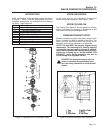
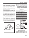
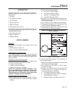
INSULATION RESISTANCE TESTERS
One kind of insulation resistance tester is shown in
Figure 1, below. Other types are commercially avail-
able. The type shown has a "Breakdown" lamp which
turns on to indicate an insulation breakdown during
the test.
One common type of tester is the "Megohmmeter"
which measures resistance in "Megohms".
Figure 1. One Kind of Hi-Pot Tester
CAUTION! When using a Megohmmeter or
any other tester, be sure to follow the manu-
facturer's instructions carefully. All Stator
leads must be isolated from other compo-
nents, especially circuit boards, before per-
forming tests. The high voltages used in test-
ing insulation resistance will damage elec-
tronic components.
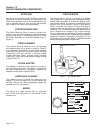
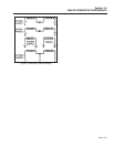
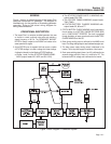
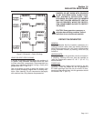
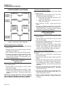
STATOR LEADS
The following leads are brought out of the Stator and
connected to various components in the unit:
WIRE# COLOR CONNECTS TO
AC1 Grey CB1A
AC2 Yellow BR1
SL1 Orange CB1B
SL2 Brown BR3
TIM1 Orange A6060 Circuit Board
TIM2 Grey A6060 Circuit Board
PS1 Red J1
PS2 Black J1
77 Brown Battery Charge Rectifier BCR
66 Brown Battery Charge Rectifier BCR
55 Black Grounding Terminal
Figure 2. Stator Leads
PREPARATION FOR TESTS
See Stator leads CHART above. Disconnect and iso-
late all Stator leads. ALL STATOR LEADS MUST BE
DISCONNECTED AND ISOLATED BEFORE START-
ING THE TESTS.
!
Page 1.4-1