


GENERATOR AC LEAD CONNECTIONS
See “Voltage Codes”. This generator may be rated
at any one of three voltages, either single-phase or
three-phase. The electrical wires in the unit’s AC con-
nection (lower) panel should be installed according to
the number of leads and the voltage/phase required
for the application. If there are any questions regard-
ing lead connection, refer to the wiring diagrams at
the back of this manual.
Voltage codes apply to the type of stator assembly
installed on a particular generator.
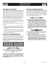
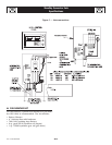
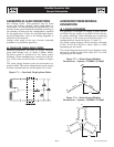
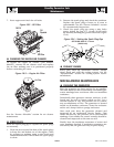
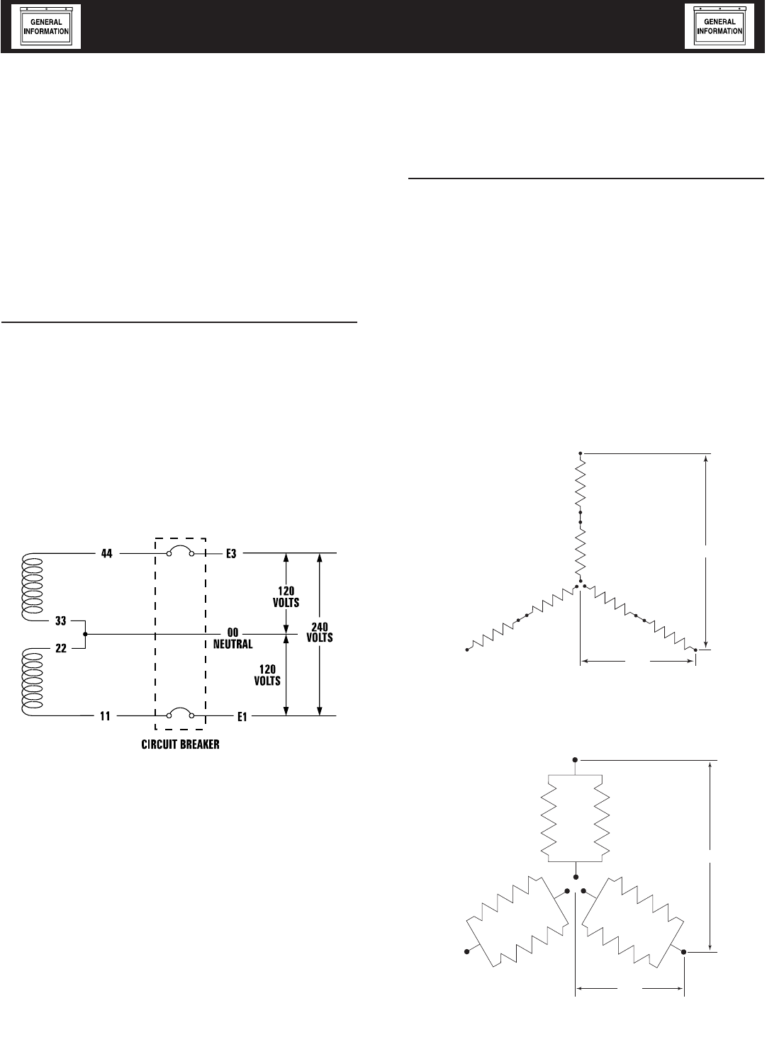
FOUR-LEAD, SINGLE-PHASE STATOR
Four-lead generators are built to supply electrical
loads with voltage code "A" (240V, 1-phase, 60Hz).
Electrical power is produced in the stator power
windings. These windings were connected at the fac-
tory to the main circuit breaker as shown in Figure
7.1.
The rated voltage between each circuit breaker ter-
minal is 240V. The rated voltage between each circuit
breaker terminal and the neutral point 00 is 120V.
Figure 7.1 — Four-lead, Single-phase Stator
ALTERNATOR POWER WINDING
CONNECTIONS
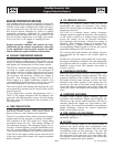
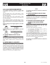
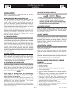
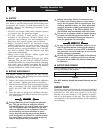
3-PHASE ALTERNATORS
The generator is designed to supply 3-phase electri-
cal loads. Electric power is produced in the alterna-
tor power windings. These windings were connected
at the factory to the main circuit breaker with a “Y”
configuration as shown in Figures 7.2 and 7.3.
The rated voltage between circuit breaker terminals
E1-E2, E1-E3 and E2-E3 is either 480V or 208V
depending on the model.
The rated voltage between each circuit breaker termi-
nal and the neutral point 00 is either 277V or 120V
depending on the model.
Figure 7.2 — Stator Power Winding
Connections - 3-phase, 277/480V (12 Lead)
E1
S1
S4
S7
S12
S11
S10
S8
S5
S2
E2
S9
S6
S3
E3
L - N
L - L
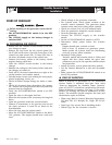
Figure 7.3 — Stator Power Winding
Connections - 3-phase, 120/208V (12 Lead)
E1
S10
S12
S4
S5
S2
S8
S11
S6
S3
S9
S7 S1
E2
E3
L - N
L - L
7-1
Standby Generator Sets
General Information
ACConn002 Rev. 0 08/05