


Section 5
ENGINE DC CONTROL SYSTEM
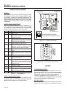
PRINTED CIRCUIT BOARD
GENERAL:
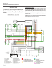
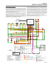
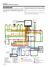
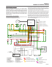
The Printed Circuit Board (PCB) mounted inside
the generator control panel is responsible for crank-
ing, startup, running and shutdown operations. The
board interconnects with other components of the DC
control system to turn them on and off at the proper
times. It is powered by fused 12 VDC power from the
unit battery.
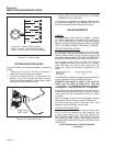
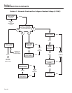
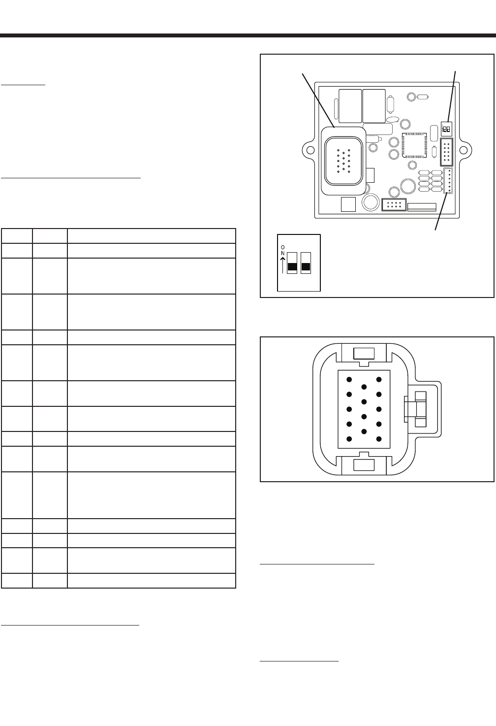
CIRCUIT BOARD CONNECTIONS:
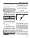
The circuit board mounts a 14-pin receptacle (J1)
and a six pin terminal (J2, see Figure 5-2). Figure
5-1 shows the 14-pin receptacle (J1), the associated
wires and the function(s) of each pin and wire.
PIN WIRE FUNCTION
1 N/A NOT USED
2 18 To Start-Stop switch. When grounded
by setting Start-Stop switch to “STOP”
engine shuts down
3 17 To Start-Stop switch. When grounded by
setting the Start-Stop switch to “START”
the engine start cycle begins.
4 15 Delivers fused 12 VDC to PCB
5 14
PCB control. During cranking and running,
supplies 12 VDC to fuel pump, choke
solenoid, choke heater, fuel solenoid
6 86 Low Oil Pressure switch / Safety shut-
down
7 85 High Temperature switch / Safety shut-
down
8 712 PCB control/Alarm led
9 56 Delivers 12 VDC to Starter Contactor
(SC) (cranking only)
10 90 To Choke Solenoid. When grounded by
the PCB the choke operates at two sec-
onds ON , two second OFF intervals
(cranking only)
11 0 Common Ground
12 N/A Not Used
13 4 Field Boost DC to the Voltage Regulator
and to the Rotor Winding
14 18A Ground to Magneto for Shutdown
Figure 5-1. – Receptacle J1
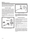
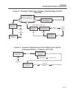
CIRCUIT BOARD DIP SWITCHES:
The circuit board mounts a pair of dip switches which
are factory set in the “OFF” (down) position. These dip
switches should remain in the factory setting.
1 2
J1 CONNECTOR
SIX PIN
J2 CONNECTOR
DIP SWITCH
DIP SWITCHES ARE FACTORY
SET IN THE “OFF” (DOWN) POSITION
1 2
Figure 5-2. – Printed Circuit Board
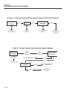
10
11
12
13
14
1
2
3
4
5
6
7
8
9
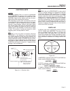
Figure 5-3. – J1 Connector, Harness End
BATTERY
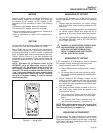
RECOMMENDED BATTERY:
When anticipated ambient temperatures will be con-
sistently above 32° F (0° C), use a 12 volts automotive
type storage battery rated 70 amp-hours and capable
of delivering at least 400 cold cranking amperes.
If ambient temperatures will be below 32° F (0° C),
use a 12 volt battery rated 95 amp-hours and having
a cold cranking capacity of 400 amperes.
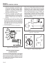
BATTERY CABLES:
Use of battery cables that are too long or too small in
diameter will result in excessive voltage drop. For best
Page 22