


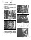
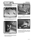
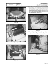
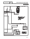
Figure 39.
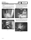
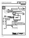
Figure 40.
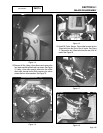
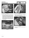
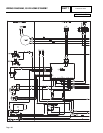
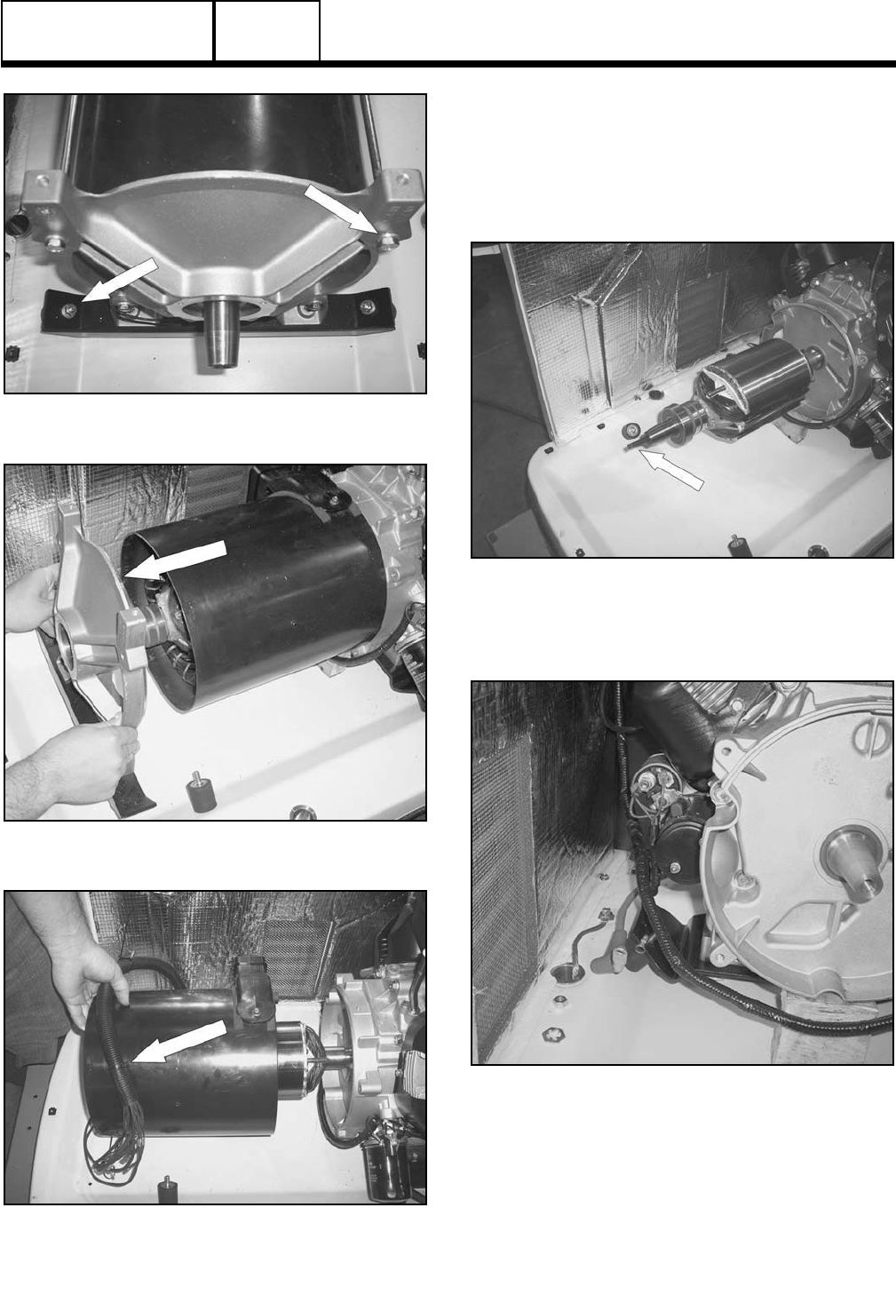
Figure 41.
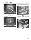
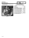
17. Rotor Removal: Cut 2.5 inches from the rotor bolt. Slot
the end of the bolt to suit a flat blade screwdriver. Slide
the rotor bolt back through the rotor and use a screw-
driver to screw it into the crankshaft. Use a 3” M12x1.75
bolt to screw into rotor. Apply torque to the 3” M12x1.75
bolt until taper breaks. See Figure 43.
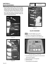
Figure 42.
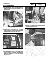
11. Remove Engine: Using a 13mm socket, remove the two
engine mount nuts with ground wires. See Figure 43.
Figure 43.
Page 161
DISASSEMBLY
SECTION 6.1
MAJOR DISASSEMBLY
PART 6