Generac
®
Power Systems, Inc. 7
1.6 SYSTEM SET LED
The “System Set” LED is lit when all of the following
conditions are true:
1. The AUTO/OFF/MANUAL switch is set to the
AUTO position.
2. The utility voltage being supplied to the unit is
being sensed by the PCB. If the utility sense volt-
age is not connected to the unit or if it is below
168 volts AC, then the system set light will flash
rapidly. This indicates that if the AUTO/OFF/
MANUAL switch is placed in the Auto position,
the generator will start.
3. The “Not In Auto” dip switch is set to the OFF
position on the control board.
4. No alarms are present, for example, low oil pres-
sure, high temperature, etc.
1.7 FUEL REQUIREMENTS
AND RECOMMENDATIONS
With LP gas, use only the vapor withdrawal
system. This type of system uses the vapors formed
above the liquid fuel in the storage tank.
The engine has been fitted with a fuel carburetion
system that meets the specifications of the 1997
California Air Resources Board for tamper-proof dual
fuel systems. The unit will run on natural gas or LP
gas, but it has been factory set to run on natural gas.
Should the primary fuel need to be changed to LP
gas, the fuel system needs to be reconfigured. See
Section 1.9 for instructions on reconfiguration of the
fuel system.
Recommended fuels should have a Btu content of at
least 1,000 Btus per cubic foot for natural gas; or at
least 2,520 Btus per cubic foot for LP gas. Ask the
fuel supplier for the Btu content of the fuel.
Fuel pressure for both natural gas and liquid
propane set ups should be 11 inches to 14 inches
of water column (0.4 to 0.5 psi) at all load ranges.
NOTE:
A separate gas line and regulator may be needed
to assure proper gas pressure (11-14”) to the gen-
erator. Low gas pressure can cause hard starting
and could affect engine durability.
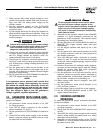
1.8 FUEL CONSUMPTION
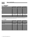
*Natural gas is in cubic feet per hour.
**LP is in gallons per hour/cubic feet per hour.
Gaseous fuels such as natural gas and liquid
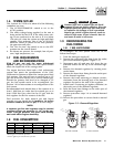
propane (LP) gas are highly explosive. Even the
slightest spark can ignite such fuels and cause
an explosion. No leakage of fuel is permitted.
Natural gas, which is lighter than air, tends to
collect in high areas. LP gas is heavier than air
and tends to settle in low areas.
1.9 RECONFIGURING THE
FUEL SYSTEM
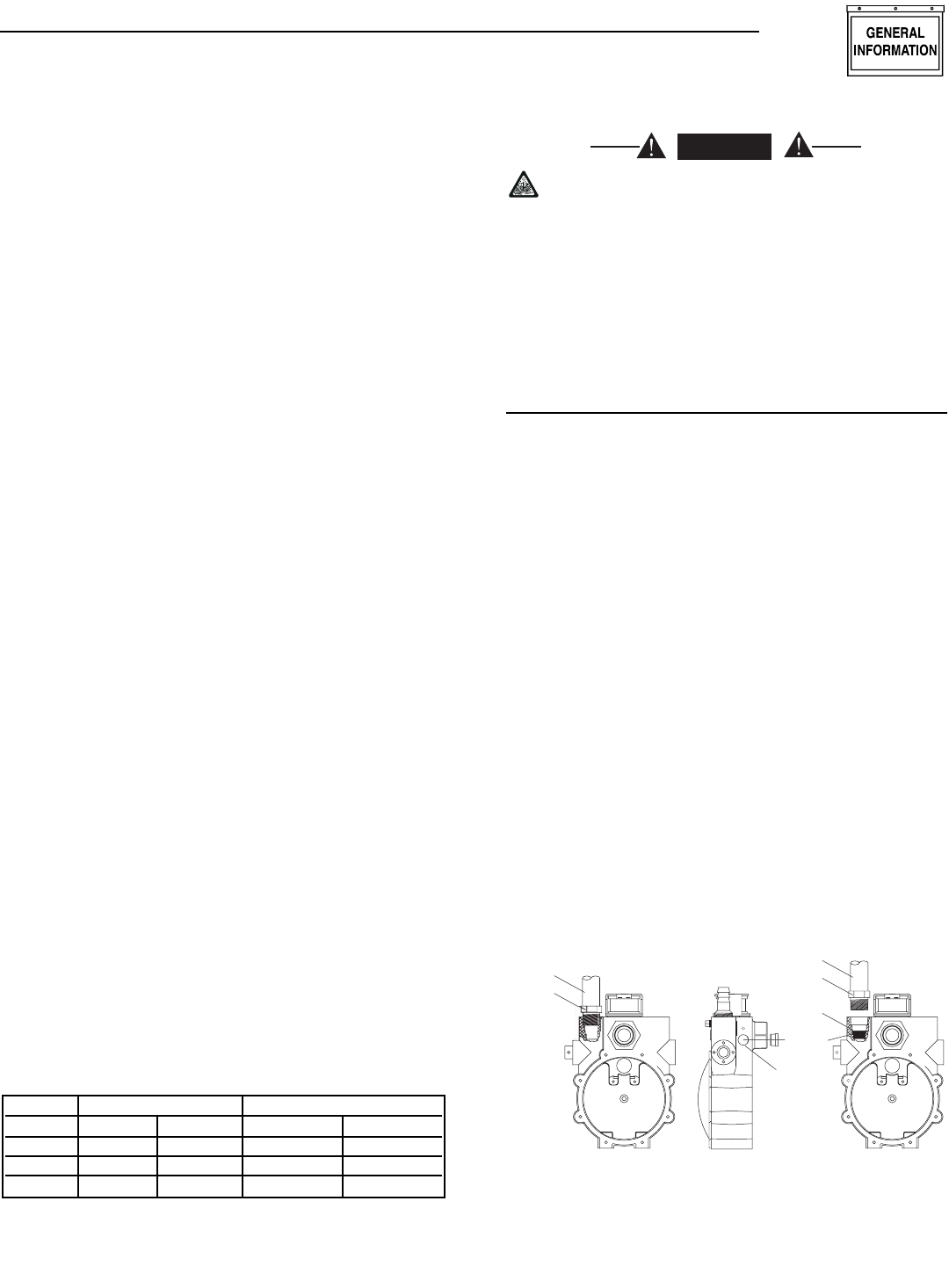
1.9.1 7 KW, 410CC ENGINE
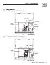
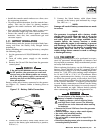
To reconfigure the fuel system from NG to LP,
follow these steps:
1. Turn the main gas supply off.
2. Remove the carburetor fuel hose from the outlet
port of the demand regulator (Figure 1.3).
3. Disconnect wire #0 and wire #14 from the gas
solenoid located on the top of the demand regu-
lator.
4. Remove the demand regulator by rotating coun-
terclockwise.
5. Remove the brass hose fitting from the outlet port
of the demand regulator.
6. Remove the brass metering jet (loosen counter-
clockwise) from the housing port of the demand
regulator located on the side of the regulator.
7. Install new LP metering jet (tighten clockwise) in
the outlet port of the demand regulator.
8. Refit the brass hose fittings to the outlet port of
the demand regulator.
9. Reverse procedure steps 1-4 to reinstall demand
regulator.
10. Reverse the procedure to convert back to natural
gas.
Figure 1.3 – Demand Regulator
F
U
EL
J
E
T
N
G
F
U
EL
S
Y
S
TE
M
LP F
U
EL
S
Y
S
TE
M
BRA
SS
H
OSE
FITTIN
G
F
U
EL H
OSE
F
U
EL H
OSE
BRA
SS
H
OSE
FITTIN
G
RE
GU
LAT
OR
H
OUS
IN
G
P
O
R
T
OU
TLE
T
P
O
R
T
◆
DANGER
Section 1 — General Information
Guardian Air-cooled 7 kW, 12 kW and 15 kW Generators
Model # Nat. Gas (*) LP Vapor (**)
1/2 Load Full Load 1/2 Load Full Load
04389 74 105 0.91/33 1.21/44.1
04456 114 185 1.34/48.9 2.17/79.0
04390 148.5 240 1.73/63.2 2.80/102.3


