


5
2.1 KNOW THE GENERATOR
Read the Owner’s Manual and Safety Rules before operating
this generator.
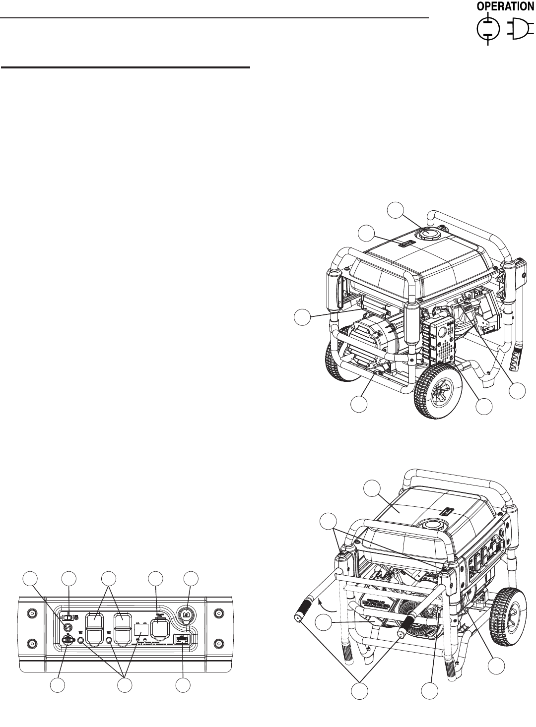
Compare the generator to Figures 4 through 6 to become
familiarized with the locations of various controls and adjustments.
Save this manual for future reference.
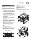
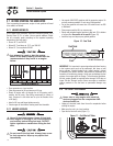
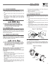
1. Battery Charger Input – This receptacle allows the capability
to recharge the 12 volt DC storage battery provided with
the 12 Volt Adaptor Plug Charger which is included in the
Accessory Box. Located behind the battery charger input is
a 1.50 Amp in-line fuse which is inside the control panel to
protect the battery.
2. 120 Volt AC, 20 Amp, GFCI Duplex Receptacle – Supplies
electrical power for the operation of 120 Volt AC, 20 Amp,
single-phase, 60 Hz electrical lighting, appliance, tool and
motor loads. It also provides protection with an Integral
Ground Fault Circuit Interrupter, complete with a press to
"Test" and "Reset" button.
3. 120/240 Volt AC, 30 Amp Locking Receptacle – Supplies
electrical power for the operation of 120 and/or 240 Volt AC,
30 Amp, single-phase, 60 Hz, electrical lighting, appliance,
tool and motor loads.
4. Circuit Breakers (AC) – Each 20 Amp receptacle is provided
with a push-to-reset circuit breaker to protect the generator
against electrical overload. The 30 Amp receptacle is protected
by a 2-pole lever circuit breaker rated at 27.1 Amps for the
XP6500E and 30 Amps for the XP8000E.
5. Hourmeter – Provides operating hours for Service Intervals.
6. Fuel Shut Off – Valve between fuel tank and carburetor. Turn
off and run carburetor out of fuel for extended storage.
7. Choke Knob – Used when starting a cold engine (Pull/Push).
8. Start/Run/Stop Switch – Controls the operation of the
generator.
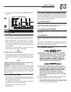
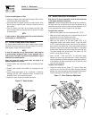
9. Air Cleaner – Filters intake air as it is drawn into the engine.
10. Fuel Tank – Tank holds 9 U.S. gallons of fuel.
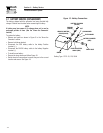
11. Grounding Lug – Ground the generator to an approved earth
ground here. See "Grounding the Generator" for details.
12. Muffler – Includes the spark arrestor and quiets the engine.
13. Battery – Powers the electric starter (End panel removed - 4
Torx Screws "T27").
Figure 4 - Control Panel
1
2 3
4 56
7 8
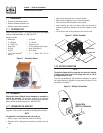
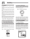
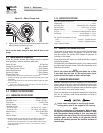
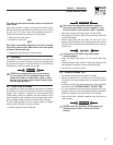
14. Handles – Pivot and retract for storage. Press the spring-
loaded button to move handles (14A).
15. Gas Cap – Fuel fill location.
16. Fuel Gauge – Shows fuel level in tank.
17. Oil Fill – Check oil level and add oil here.
18. Recoil Starter – Use to start engine manually.
19. Spark Plug – Ignites Air/Fuel Mixture (End & Side panel
removed - 4 Torx Screws "T27").
Figure 5 - Generator Controls
12
11
13
15
16
19
Figure 6 - Generator Controls
10
14A
14
18
17
9
Section 2 – Operation
Portable Generator System