


Activation and Startup
Owner’s Manual for Stationary Diesel Generators 17
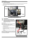
5. Press MANUAL on the control pad. The engine will crank and start.
6. Allow the engine to warm up for a few minutes.
7. Move the Main Circuit Breaker switch on the generator control panel up to the ON (or closed) position. The
switch is now powered by the standby generator.
8. Turn ON the circuit breaker/electrical loads powered by the generator.
9. Connect a calibrated AC voltmeter and a frequency meter across terminal lugs E1, E2, and E3 (if three phase).
Voltage should be approximately unit rated voltage. Check with clamp on amp meter to ensure unit is not over-
loaded.
10. Let the generator run at full rated load for 20-30 minutes. Listen for unusual noises, vibration or other indications
of abnormal operation. Check for oil leaks, evidence of overheating, etc.
11. When testing under load is complete, turn OFF electrical loads.
12. Move the Main Circuit Breaker switch on the generator control panel up to the OFF (or open) position.
13. Allow the engine to run at no-load for 2-5 minutes.
14. Press OFF on the control pad to shut the engine down. A red LED illuminates to confirm that the system is in the
OFF mode.
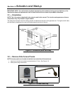
3.8.5— Check Automatic Operation
To check the system for proper automatic operation, proceed as follows:
1. Verify that the generator is OFF. A red LED on the control pad illuminates to confirm that the system is in the OFF
mode.
2. Install front cover of the transfer switch.
3. Turn ON the utility power supply to the transfer switch, using the means provided (such as a utility main line cir-
cuit breaker).
NOTE: Transfer Switch will transfer back to utility position.
4. Move the Main Circuit Breaker switch on the generator control panel up to the ON (or closed) position.
5. Press AUTO on the control pad. The system is now ready for automatic operation.
6. Turn OFF the utility power supply to the transfer switch.
With the generator ready for automatic operation, the engine will crank and start when the utility source power is turned
OFF after a 10 second delay (factory default setting). After starting, the transfer switch connects load circuits to the
standby side. Let the system operate through its entire automatic sequence of operation.
With the generator running and loads powered by generator AC output, turn ON the utility power supply to the transfer
switch. The system transfers back to the utility position and then runs through the cool down cycle and shuts down.
3.9 — Final Instructions
1. Use key to install side access panels.
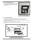
2. Close viewing window.
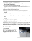
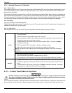
NOTE: Obtain viewing window hasp, if not installed. See
Figure 3-7. With the retaining tab at the bottom, insert
square end of hasp into slot below viewing window.
Push on hasp until it snaps in place. Gently pull on hasp
to verify that it will not come free.
3. Install customer supplied padlock into hasp.
Figure 3-7. Install Viewing Window Hasp