


10
Recreational Vehicle Generator
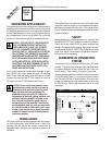
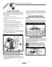
Induction type motors (such as those that run the vehicle’s
furnace fan, refrigerator, air conditioner, etc.) need about 2-
1/2 time more watts of power for starting than for running
(for a few seconds during motor starting). Be sure to allow
for this when connecting electrical loads to the generator.
First, figure the watts needed to start electric motors in the
system. To that figure, add the running wattages of other
items that will be operated by the generator.
Do not apply heavy electrical loads for the first two or three
hours of operation.
ADDITIONAL INFORMATION
This section discusses some the the engine protective devices,
overload protection and breaking in a new generator.
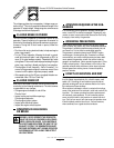
AUTOMATIC LOW OIL PRESSURE
SHUTDOWN
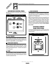
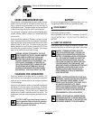
The engine is equipped with a normally-closed (N.C.) oil pres-
sure switch (Figure 4). Engine oil pressure holds the switch
open during cranking and operation. Should oil pressure drop
below a pre-set level, the switch contacts close and the engine
automatically shuts down.
HIGH TEMPERATURE SHUTDOWN
A temperature switch (Figure 4) with normally-open (N.O.) con-
tacts is mounted near the oil filter. If engine temperature were
to exceed about 284°F (140°C), the switch contacts close
and the engine shuts down.
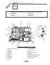
Figure 4 — Switches for Engine
Safety Shutdown
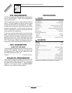
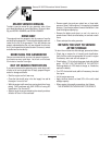
FIELD BOOST
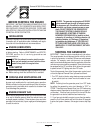
The Controller Circuit Board houses a field boost diode and
resistor which are part of a “field boost” circuit (Figure 5).
During engine cranking only, a positive DC (battery) voltage
is delivered through the diode, resistor, brushes and slip rings,
and the generator rotor. Application of this voltage to the
rotor “flashes the field” whenever it is started. Flashing of the
field each time the generator starts makes sure that a suffi-
ciently strong magnetic field is available to produce “pick-up”
voltage in the stator windings.
Figure 5 — Field Boost Circuit
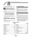
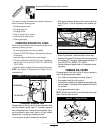
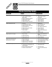
OVERVOLTAGE PROTECTION
A solid state voltage regulator (Figure 6) controls the gener-
ator’s AC output voltage. This regulator supplies an excitation
current to the rotor. By regulating the rotor’s excitation cur-
rent, the strength of its magnetic field is regulated and, in
turn, the voltage delivered to connected electrical loads is
controlled. When the AC frequency is 60 Hz, voltage is reg-
ulated at 120 volts (voltage-to-frequency ratio is 2-to-1).
Figure 6 — Solid State Voltage Regulator
Generac NP-50LPG Recreational Vehicle Generator
HIGH TEMPERATURE
SWITCH
LOW OIL PRESSURE SWITCH
GENERAC
®
CORPORATION