


7
5500 Watt Heavy Duty Generator
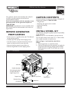
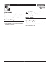
GROUNDING THE
GENERATOR
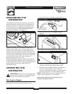
The National Electrical Code requires that the frame and
external electrically conductive parts of this generator be
properly connected to an approved earth ground. Local
electrical codes may also require proper grounding of the
unit. For that purpose, a GROUNDING WING NUT is
provided on the generator end (Figure 3).
Generally, connecting a No. 12 AWG (American Wire
Gauge) stranded copper wire to the grounding wing nut
and to an earth–driven copper or brass grounding rod
(electrode) provides adequate protection against electrical
shock. Be careful to keep the grounding wire attached after
connecting the stranded copper wire. However, local codes
may vary widely. Consult with a local electrician for
grounding requirements in your area.
Properly grounding the generator helps prevent electrical
shock if a ground fault condition exists in the generator or
in connected electrical devices. Proper grounding also helps
dissipate static electricity, which often builds up in
ungrounded devices.
OPERATING THE
GENERATOR
CAUTION! Never start or stop the engine with
electrical loads connected to the receptacles AND
with the connected devices turned ON.
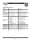
Starting the Engine
Disconnect all electrical loads from the generator. Use the
following start instruction steps by numerical order:
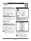
1. Turn the fuel valve to the “On” position (Figure 4).
2. Place the choke lever in the “Choke” position
(Figure 5).
3. Set the rocker switch to “On” position (Figure 6).
4. Grasp the recoil handle and pull slowly until slight
resistance is felt.Then pull rapidly to start engine.
5. Move choke lever to “Run” position a short distance at
a time over several seconds in warm weather or
minutes in cold weather. Let engine run smoothly before
each change. Operate with choke in “Run” position.
NOTE: If engine still fails to start, see engine manual.This
engine may be equipped with a low oil device.
Refer to the engine owner’s manual for more
detailed starting instructions.
Fuel Valve is shown
in the On position
Figure 4 — Fuel Valve
Figure 5 — Choke Lever
Figure 6 — Rocker Switch
Figure 3 — Grounding Wing Nut
Grounding
Wing Nut