


4
1.1 INTRODUCTION
This manual has been prepared especially for the
purpose of familiarizing personnel with the design,
application, installation, and operation of the appli-
cable equipment. Read the manual carefully and
comply with all instructions. This will help to prevent
accidents or damage to equipment that might other-
wise be caused by carelessness, incorrect applica-
tion, or improper procedures.
Every effort has been expended to make sure that the
contents of this manual are both accurate and cur-
rent. The manufacturer, however, reserves the right
to change, alter or otherwise improve the product at
anytime without prior notice.
1.2 EQUIPMENT DESCRIPTION
The PowerMaster assembly is used to automatically
disconnect selected loads from the generator output
when a high demand appliance, such as a central air
conditioning system, is started, easing the burden on
the generator. The selected loads will then be auto-
matically reconnected to the generator output once
the high demand appliance is turned off. The selected
loads will only be disconnected if the transfer switch
is in the generator position when the high demand
appliance is started.
A total of up to two 240V, 30Amp loads can be con-
nected to the system, and be controlled by a total of
up to two 24Vac control signals from various high
demand appliances.
Once installation is completed, the PowerMaster
assembly will operate automatically without any need
for user intervention or routine maintenance.
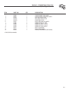
1.3 UNPACKING THE BOX
Carefully unpack the box and check for any damage
that may have occurred during shipping. Check to
make certain all the following items are included:
Qty. Part No. Description
1 0F9110 PowerMaster assembly
1 0G0734 Manual, installation and
operating instructions
2 084464 Auxiliary contact switches
4 027770 Screws for mounting the
auxiliary contact switches
4 043182 Washers for mounting the
auxiliary contact switches
4 059051 Lug, Ring, #8 screw, 10-
12AWG
4 079679 Lug, Fast-on, 3/16 inch, 18-
22AWG
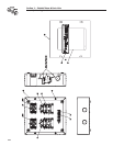
1.4 ENCLOSURE DETAILS
The enclosure is a National Electrical Manufacturer’s
Association (NEMA) 1 type. NEMA 1 type enclosures
are suitable only for indoor mounting.
2.1 INTRODUCTION TO INSTALLATION
This equipment has been wired and tested at the fac-
tory.
Installing this assembly includes the following pro-
cedures:
Mounting the enclosure
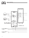
Connecting the source voltage(s) and load(s)
Connecting the control circuit(s)
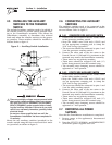
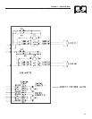
Installing the Auxiliary switches to the transfer
switch
Connecting the Auxiliary switches
Restoring all power supplies
Testing the PowerMaster operation
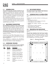
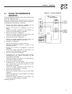
2.2 MOUNTING THE ENCLOSURE
Mounting dimensions for the enclosure are shown in
figure 1.
The enclosure should be wall mounted in an indoor
location only, preferably near the circuit breaker
load center. Mount the assembly vertically to a rigid
supporting structure. To prevent distortion, level all
mounting points. If necessary, use washers behind
the mounting holes to level the assembly.
Figure 1 — Mounting Dimensions
254
228.6
25.4
177.8
22
210
•
•
•
•
•
•
•
Section 1 — General Information
PowerMaster Technical Manual