


4
1.1 UNPACKING
Remove all packaging material.•
Remove separate accessory box.•
Remove the generator from carton.•
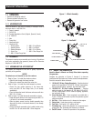
1.1.1 ACCESSORY BOX
Check all contents. If any parts are missing or damaged, locate an
authorized dealer at 1-888-436-3722.
1 - Owner’s manual•
1 - Oil SAE 30•
3 - Product Registration Cards (English, Spanish, French)•
2 - 8” WHEELS•
1 - Axle•
1 - Frame Foot•
1 - Handle with grip•
1 - Hardware Bag•
1 - Plastic Spacer 2 - M8-1.25 x 40 Bolts
1 - Handle Bracket 1 - M6-1.0 x 40 Bolt
2 - Rubber Bumpers 2 - M8-1.25 x 16 Bolts
2 - Cotter Pins 1 - M6-1.0 Hex Flange Nut
2 - M8-1.25 Hex Flange Nuts
1.2 ASSEMBLY
The generator requires some assembly prior to using it. If problems
arise when assembling the generator, please call the Generator
Helpline at 1-888-436-3722.
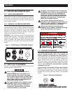
1.2.1 ASSEMBLING THE ACCESSORY KIT
The wheels are designed to the unit to greatly improve the
portability of the generator.
NOTICE:
The wheels are not intended for over-the-road-use.
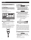
1. Refer to Figure 1 to install the wheels as shown.
• Slide the axle through the frame brackets.
• Slide on the wheels then install the cotter pins.
2. Refer to Figure 1 to install the wheel bumpers as shown.
• Secure the two rubber bumpers to the frame foot
using two M8-1.25 Hex Flange Nuts (if not already
assembled).
• Place the frame foot under the frame and secure with two
M8-1.25 x 16 bolts.
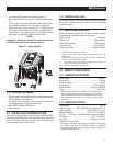
3. Refer to Figure 2 to install the handle assembly as shown.
• Install the handle bracket to the frame using two M8-1.25
x 40 bolts (if not already assembled).
• Slide the plastic spacer onto the handle assembly then
align with the holes in the handle bracket (if not already
assembled).
• Secure the handle assembly to the handle bracket using
the M6-1.0 x 40 bolt and one M6-1.0 hex flange nut.
Figure 1 – Wheel Assembly
Figure 2 – Handle Kit
M8-1.25 x 40
BOLTS
1 X M6-10 HEX FLANGE NUT
1x HANDLE W/GRIP
1x PLASTIC SPACER
1x M6-1.0X40 BOLT
1x HANDLE BRACKET
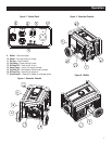
2.1 KNOW THE GENERATOR
Read the Owner’s Manual and Safety Rules before operating
this generator.
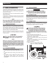
Compare the generator to Figures 3 through 6 to become
familiarized with the locations of various controls and adjustments.
Save this manual for future reference.
1. 120 Volt AC, 20 Amp, Duplex Receptacle – Supplies electrical
power for the operation of 120 Volt AC, 20 Amp, single-phase,
60 Hz electrical lighting, appliance, tool and motor loads.
2. 120/240V AC, 20 Amp Locking Receptacle – Supplies
electrical power for the operation of 120 and/or 240 volt AC,
20 amp, single-phase, 60 Hz, electrical lighting, appliance,
tool and motor loads.
3. Circuit Breakers (AC) – Each receptacle is provided with a
2-pole, 14 amp circuit breaker to protect the generator against
electrical overload.
4. Air Filter – Filters intake air as it is drawn into the engine.
5. Choke Knob – Used when starting a cold engine.
6. Fuel Tank – Tank holds 4 U.S. gallons of fuel.
7. Grounding Lug – Ground the generator to an approved earth
ground here. See "Grounding the Generator" for details.
8. On/OFF Switch – Controls the operation of the generator.
General Information