


1.10 SPECIFICATIONS
1.10.1 GENERATOR SPECIFICATIONS
1.10.2 ENGINE SPECIFICATIONS
Make ................................................................................Chrysler
Displacement ..................................................................3.9 liters
Cylinder Arrangement ..............................................................V-6
Valve Arrangement ..............................................Overhead Valve
Firing Order ................................................................1-6-5-4-3-2
Number of Main Bearings............................................................4
Compression Ratio............................................................9.1 to 1
No. of Teeth on Flywheel ........................................................164
Ignition Timing at 1800 rpm..............................30 degrees BTDC
Spark Plug Gap ..............................................1.01mm (0.040 in.)
Recommended Spark Plugs
Champion ....................................................................RC12LC4
Oil Pressure....................................................................30-80 psi
Crankcase Oil Capacity........................4.0 U.S. quarts (3.8 liters)
Recommended Engine Oil........................................SAE 15W-40
Type of Cooling System ..................Pressurized, closed recovery
Cooling Fan ..............................................................Pusher Type
Cooling System Capacity..................5.0 U.S. gallons (19.3 liters)
Recommended Coolant ............................Use a 50-50 mixture of
ethylene glycol base
and de-ionized water.
1.11 FUEL CONSUMPTION
Natural Gas:
% of Load 25% 50% 75% 100%
m
3
/hr 4.1 7.7 11.0 14.2
ft
3
/hr 143.1 271.1 388.5 502.0
LP
Vapor:
% of Load 25% 50% 75% 100%
m
3
/hr 1.7 3.3 4.7 6.0
ft
3
/hr 60.7 115.0 164.9 213.0
NOTE:
Fuel consumption is given at rated maximum con-
tinuous power output when using natural gas
rated at 1000 Btu per cubic foot. LP gas is rated
at 2520 Btu per cubic foot. Actual fuel consump-
tion obtained may vary depending on such vari-
ables as applied load, ambient temperature,
engine conditions and other environmental fac-
tors.
Fuel pressure for a natural gas set up should be five
inches to 14 inches of water column (0.18 to 0.5
psi) at all load ranges.
Fuel pressure for an LP vapor set up should be 11
inches to 14 inches of water column (0.4 to 0.5
psi) at all load ranges.
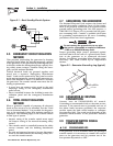
1.12 RECONFIGURING THE FUEL
SYSTEM
NOTE:
All models are configured for natural gas from the
factory.
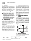
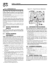
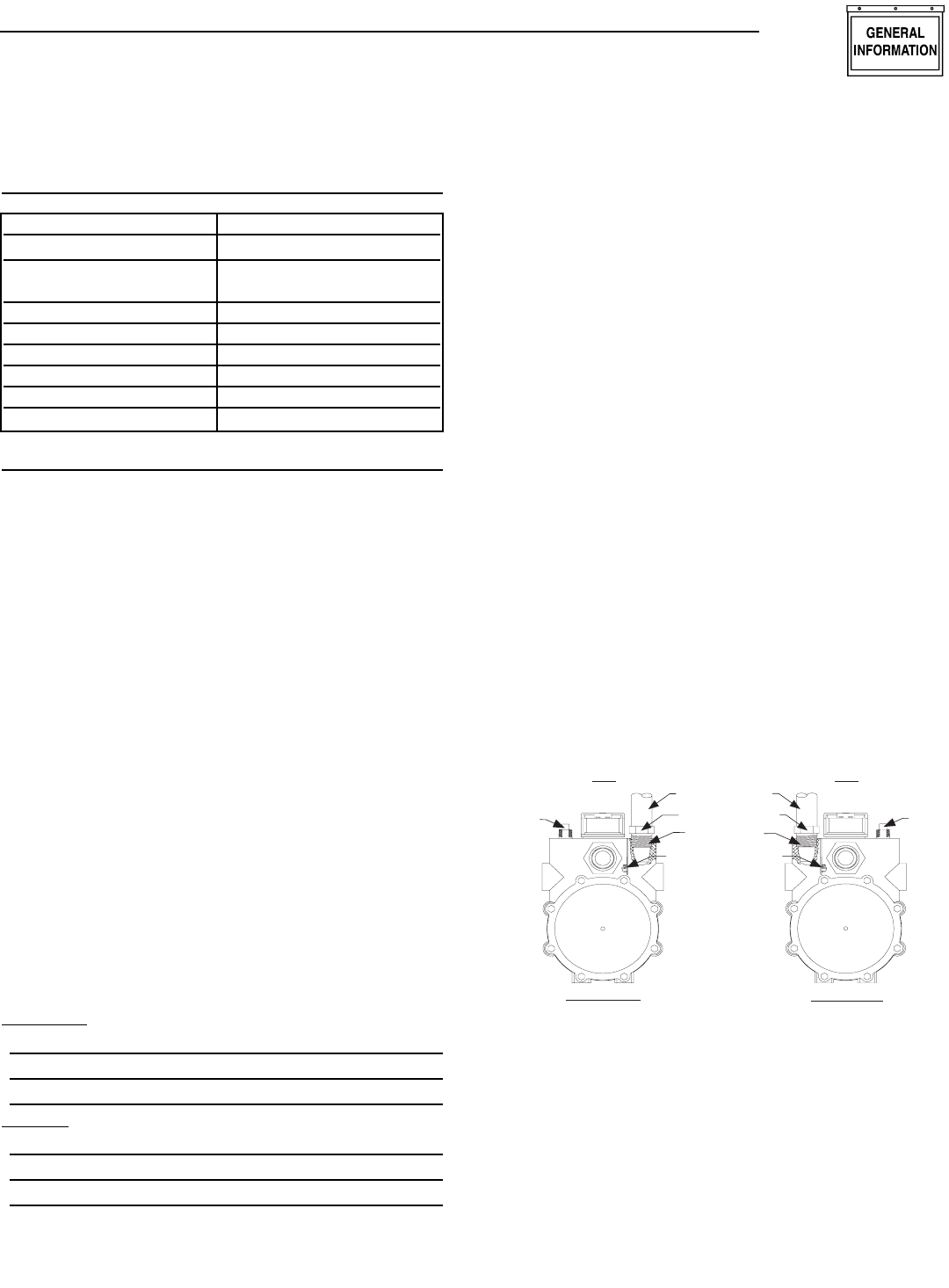
To reconfigure the fuel system from NG to LP vapor,
follow these steps:
1. Turn the main gas supply off.
2. Remove the carburetor fuel hose from the outlet
port (Port 1) of the demand regulator (Figure
1.8).
Figure 1.8 — Reconfigure the Fuel System
3. Remove the brass hose fitting from the outlet port
(Port 1) of the demand regulator.
4. Remove pipe plug from Port 2.
5. Install brass hose fitting into Port 2.
6. Install pipe plug into Port 1.
7. Connect carburetor gas hose to brass fitting.
8. Tighten all clamps and plugs.
9. Make sure fuel supply is of the proper pressure
and type for configuration.
10. Reverse the procedure to convert back to natural
gas.
NG FUEL SYSTEM
LP FUEL SYSTEM
Port 1
Port 2
FUEL HOSE
BRASS HOSE
FITTING
HOUSING
PORTS
OUT
PORT 2
PLUG
FUEL HOSE
BRASS HOSE
FITTING
HOUSING
PORTS
PLUG
OUT
PORT 1
Section 1 — General Information
QUIETSOURCE
™
40kW Liquid-cooled Generators
Generac
®
Power Systems, Inc. 7
Single-phase
Model 005012-0
Rated Max. Cont. 37 (NG), 40 (LP)
AC Power Output (kW)
Rated voltage (volts) 120/240
No. of Rotor Poles 4
Driven Speed of Rotor 1800
Rotor Excitation System Direct excited brush type
Type of Stator 4 Wire
Rotor/Stator Insulation Class F/H