


13
Section 2 — Post Installation Start-up and Adjustments
Air-cooled 7 kW, 12 kW and 15 kW Generators
6. When frequency is correct at no load, check the
AC voltage reading. If voltage is incorrect, the volt-
age regulator may require adjustment.
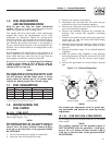
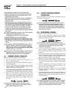
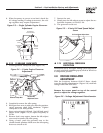
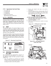
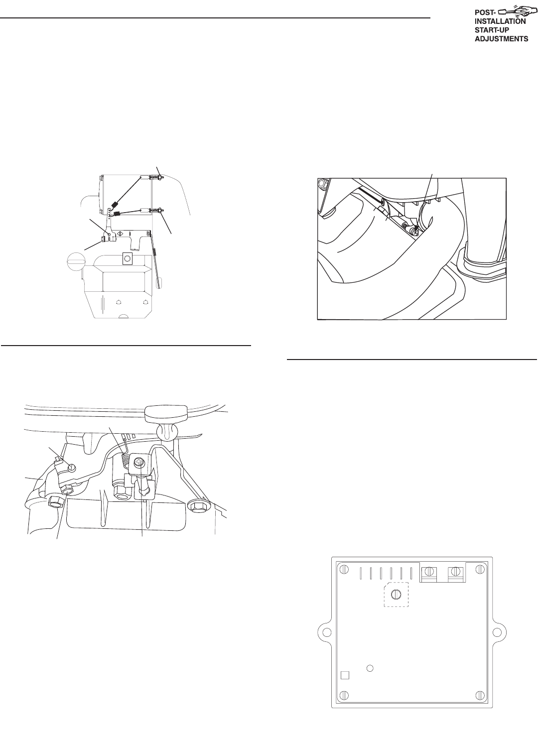
Figure 2.3 — Single Cylinder Engine Governor
Adjustment
GOVERNOR
SHAFT
PRIMARY
ADJUST
SCREW
GOVERNOR
CLAMP
BOLT
SECONDARY
ADJUST SCREW
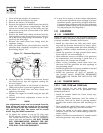
2.7.2 12 KW AND 15 KW UNITS
1. Loosen governor clamp bolt (See Figure 2.4).
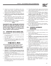
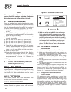
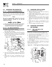
Figure 2.4 — V-twin Engine Governor
Adjustment
Governor Clamp Bolt
Governor
Shaft
(Rotate
Clockwise)
Idle Spring
No Load Idle
Adjustment Screw
2. Completely remove the idle spring.
3. With governor arm at wide open throttle position,
rotate governor shaft fully clockwise. Tighten
clamp bolt to 84 inch-pounds.
4. Start unit and apply full load. Use full load speed
adjust screw (Figure 2.5) to adjust frequency to
58 Hz.
5. Remove load, stop engine, loosen the idle adjust
screw and reconnect the idle spring.
6. Using a hand, push the governor arm to the
closed throttle position. Make sure the idle spring
does not stretch at all.
7. Restart the unit.
8. Slowly turn the idle adjust screw to adjust the no-
load idle frequency to 63-63.5 Hz.
9. The governor is now set.
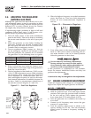
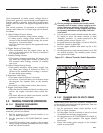
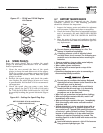
Figure 2.5 — V-twin Full Load Speed Adjust
Screw
Full Load Speed Adjust Screw
2.7.3 ADDITIONAL CORROSION
PROTECTION
Periodically spray all engine linkage parts and brack-
ets with corrosion inhibiting spray such as WD-40 or
a comparable product.
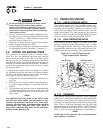
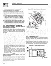
2.8 VOLTAGE REGULATOR
ADJUSTMENT
With the frequency between 62-63.5 Hertz, slowly
turn the slotted potentiometer (Figure 2.6) until line
voltage reads 244-252 volts.
NOTE:
Remove the access panel on top of the control
panel to adjust the voltage regulator.
Figure 2.6 – Voltage Adjustment Potentiometer