


Generac
®
Power Systems, Inc. 25
Section 6 – Installation
QUIETPACT 55, 65, and 75 Recreational Vehicle Generators
6.2.4 ACOUSTICS
For additional noise abatement, the installer may
wish to consider the following:
• Using special sound insulating materials.
• Construction of a special noise abatement com-
partment.
NOTE:
Any method used to reduce noise must not
adversely affect the flow of cooling and ventilating
air into or out of the compartment.
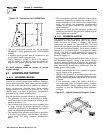
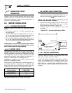
In addition to the effective use of sound insulating
materials, construction of a special noise abatement
compartment might be considered to reduce noise
levels. Such a compartment might be constructed as
follows (Figure 6.7):
• Use 5/8-inch thick or 3/4-inch thick plywood in the
compartment.
• Construct the compartment floor of a double thick-
ness of 5/8-inch or 3/4-inch plywood.
• Line the compartment interior walls and floor, as
well as the underside of the floor, with 26-gauge
galvanized steel.
• Vapor seal all compartment seams and joints.
• Over the galvanized steel lining, install a combina-
tion of acoustical materials as mentioned in
Section 6.2.3.
To prevent fire or explosion, do not install any
insulation or other absorbent materials on the
interior or underside of the compartment floor.
• Seal all compartment door edges to prevent noise
leakage around the door perimeter.
• Line the compartment door interior (except for air
openings) with suitable, fireproof sound insulation
(such as 1-inch (25 mm) thick fiberglass with a 2-
pound density).
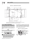
Figure 6.7 – Typical Noise Abatement
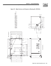
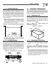
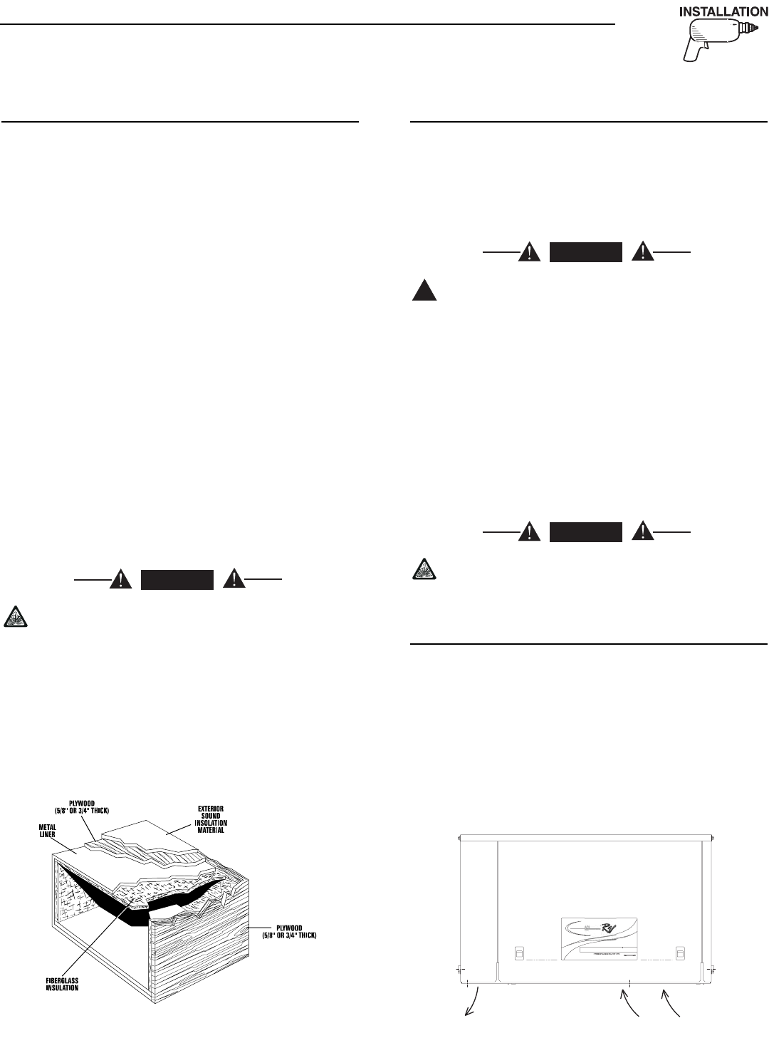
6.2.5 COMPARTMENT FLOOR CUTOUTS
You must provide openings in the generator compart-
ment for the following items (Figure 6.8, Page 26):
• Engine exhaust and cooling air outlets
• Generator cooling air inlet
• Four holes for passage of generator mounting
bolts. See Section 6.1.4 (Page 23).
Fuel lines and exhaust piping must not pene-
trate into the vehicle living area.
6.3 COOLING AND VENTILATING AIR
It is absolutely essential that an adequate flow of air
for cooling, ventilating and engine combustion be
supplied to the generator set. Without sufficient air-
flow, the engine/generator quickly overheats. Such
overheating can cause serious operating difficulties
and also may cause fire and personal injury. The
installer must make sure that sufficient air is avail-
able to the generator for cooling, ventilating and com-
bustion. The installer also must provide for a path
for exhausting the cooling air to the exterior of a com-
partment, if so equipped.
Never use discharged cooling air for heating or
permit such air to enter the vehicle interior. This
air contains deadly carbon monoxide gas and
other poisonous, flammable or explosive gases.
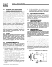
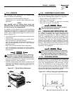
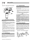
6.3.1 GENERATOR AIRFLOW
Engine operation drives cooling fans for the two-stage
cooling air system. A pressure fan draws cooling air
into the top of the generator (Figure 6.9). This airflow
cools the engine/generator and electronic compo-
nents. The second part of the cooling system, a suc-
tion fan, draws air that is heated from a hot engine
into a collector pan at the base of the unit. This heat-
ed air (although cooler than exhaust muffler) is then
deflected out the bottom toward the ground.
Figure 6.9 – Airflow Through Engine/Generator
b
y
Generac Power S
y
st
e
Q
UIETPAC
T
IND
US
TRIA
L
55G
GU
ARDI
A
◆
DANGER
!
DANGER
◆
DANGER
◆