


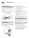
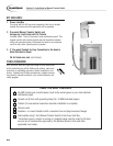
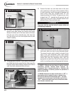
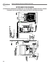
7a. Lift cover of the power inlet box and remove the
internal cover plate screws and internal cover plate.
Remove the knock out in the lower center of the box.
From the rear of the connection box, feed wires into
box. Slip the lock nut over wires tighten securely onto
conduit coupling.
7b. Using appropriate fasteners, mount power inlet box over
pre-drilled hole to fully conceal the hole. Seal around the
hole and conduit with insulating material and/or silicone
caulk from both outside and inside of house.
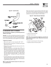
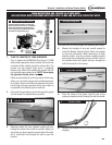
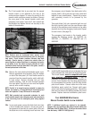
8. Connect the black, red, and white wires to the same
color coded lugs on the back of the receptacle. Failure
to match wires may result in damage to generator and
house wiring. Strip wire insulation back 1/2” and
torque lug screws to 25 in/lbs. The green wire is to be
stripped back 1/2”, inserted into the ground lug and
torque lug screw to 25 in/lbs. Reinstall internal cover
plate and screw. Close and lock cover.
The power inlet box must be locked to ensure safety and
to discourage tampering.
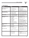
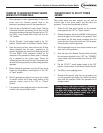
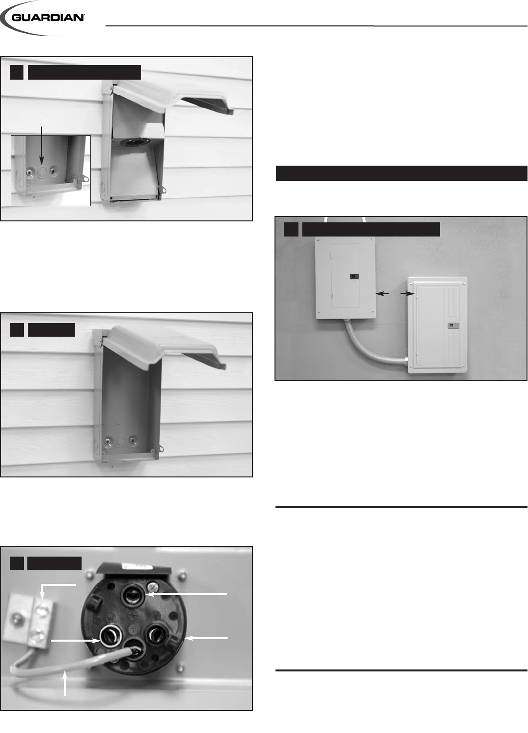
9. Locate manual transfer switch with built-in emergency
load center within one foot of main distribution panel.
The manual transfer switch should be located to the
right of the main distribution panel. Hold transfer
switch against the mounting surface. Level the transfer
switch and mark the mounting holes. Drill the
appropriate size pilot holes. Mount the manual transfer
switch to mounting surface with appropriate fasteners.
ƽ DANGER: Although you may choose to perform electrical
connections yourself, Generac Power Systems, Inc.
recommends that a licensed electrician or individual with
complete knowledge of electricity perform the procedures in
sections 10a and 10b.
ƽ DANGER: Switch service main circuit breaker to “OFF” or
open position prior to removal of cover or removal of any
wiring of the main electrical distribution panel. The wires
connected to the service main circuit breaker remain live or
“HOT”. Avoid contact with these wires and the service main
circuit breaker connection lugs.
Mount Box
7b
22
Section 5—Installation for Manual Transfer Switch
--- ƽ WARNING ƽ ---
Mounting Manual Transfer Switch
9
Prepare Box For Connections
7a
1ft
8
Knockout
Receptacle
Black
Red
White
Green
Existing Wire