


6
Section 2 – Operation
Commercial-Industrial-Residential Portable Generator System
OPERATION
2.1 KNOW THE GENERATOR
Read the
Owner’s Manual
and
Safety Rules
before
operating this generator.
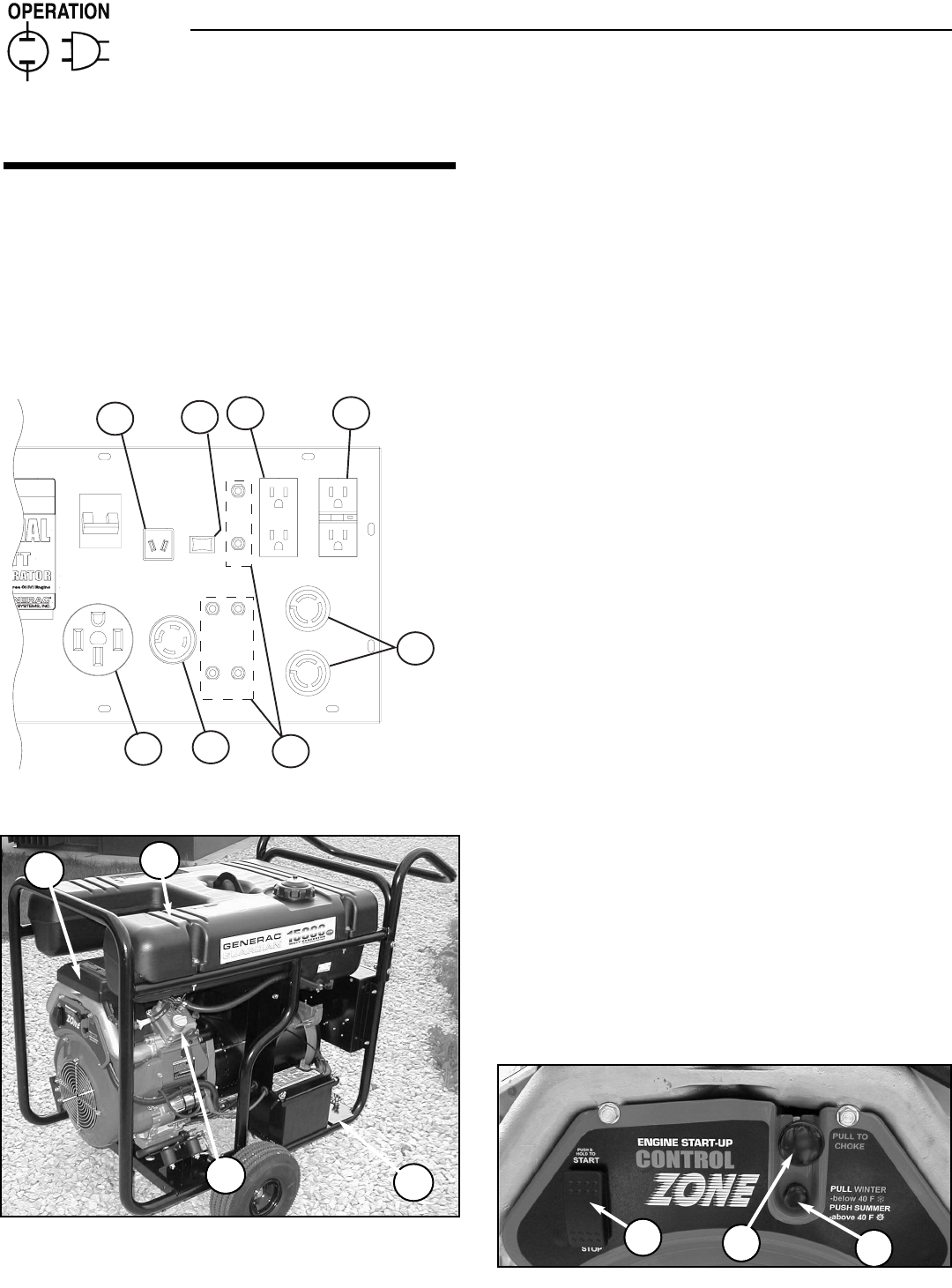
Compare the generator to this illustration to become familiarized with
the locations of various controls and adjustments. Save this manual for
future reference.
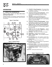
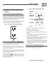
1) 12 Volt DC, 10 Amp Receptacle –
This receptacle allows
the capability to recharge a 12 volt DC storage battery with
provided battery charge cables.
2) 120 Volt AC, 20 Amp, Duplex Receptacle –
Supplies
electrical power for the operation of 120 Volt AC, 20 Amp,
single-phase, 60 Hz electrical lighting, appliance, tool and
motor loads.
3) 120 Volt AC, 20A Duplex GFCI Receptacle –
Supplies ground fault protected electrical power for operation of
120 volt AC 20 amp, single-phase, 60 Hz electric lighting,
appliances, tools and motor loads.
4) 120 Volt AC, 30 Amp Locking Receptacle –
Supplies
electrical power for the operation of 120 Volt AC, 30 Amp, single-
phase, 60 Hz electrical lighting, appliance, tool and motor loads.
5) 120/240 Volt AC, 30 Amp Locking Receptacle –
Supplies electrical power for the operation of 120 and/or 240 Volt
AC, 30 Amp, single-phase, 60 Hz, electrical lighting, appliance,
tool and motor loads.
6) 120/240 Volt AC, 50 Amp Receptacle –
Supplies
electrical power for the operation of 120/240 Volt AC, 50 Amp,
single-phase, 60 Hz, welder or motor loads.
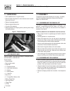
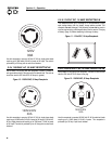
7) Air Cleaner –
Filters intake air as it is drawn into the engine.
8) Choke Knob –
Used when starting a cold engine.
9) Winter / Summer Valve –
See “Cold Weather Operation.”
(Section 2, page 12.)
10) Circuit Breakers
(AC) – Each receptacle is provided with a
push-to-reset circuit breaker to protect the generator against
electrical overload.
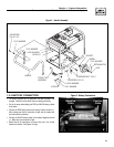
11) Fuel Tank –
Tank holds 16 U.S. gallons of fuel.
12) Grounding Lug –
Ground the generator to an approved earth
ground here. See page 9 for details.
13) Idle Control Switch –
The idle control runs the engine at
normal (high) speeds when there is an electrical load present and
runs the engine at idle (low) speeds when a load is not present.
14) Start/Run/Stop Switch –
Controls the operation of the
generator.
15) Oil Fill –
Use this point to add oil to engine.
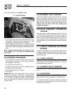
7
11
12
15
9
8
14
Figure 5 - Generator Controls
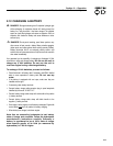
Figure 6 - Engine Control Panel
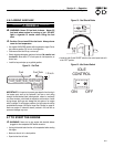
30A
120V
20A
GFCI
120V
20A
120V
CIRCUIT BREAKERS - PUSH TO RESET
HOUR METER
10A
ON OFF
IDLE
CONTROL
12Vdc
120V/240V
50A
120V/240V
30A
50A
30A
TEST RESET
TESTRESET
30A
30A30A
20A
20A
GFCI
120V
30A
1/10
HOURS
QUARTZ
1
2
3
4
5
6
10
13
Figure 4 - Control Panel