


1312
GG
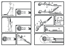
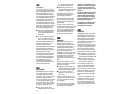
5.1 Assembly of the guide
handle (fig. A)
The three-position guide handle
1
is mounted onto the unit and
secured with 2 screws. (Captive
screws integrated in the handle.)
5.2 Basic working position
settings (fig. B-E)
The Telescopic Hedge Trimmer
has three basic settings. These
are marked
!
to
§
on the blade
head and the handle:
!
Trimming hedges from the
side at a distance from the
standing position, eg. to reach
over flower beds (fig. B/B1).
Not
e:
Telescopic handle retracted.
"
For trimming extremely low
hedges, or eg. ground blan-
kets, while standing upright
(fig. C/C1).
Not
e: Telescopic handle
extended to the appropriate
length for upright working.
§
For trimming high hedges
up to approx. 2.5 m from
the ground without the need
for a ladder or scaffolding
(fig. D/D1).
Note: Telescopic handle ex-
tended to the appropriate
length. Control of the Tele-
scopic Hedge Trimmer is
within arm’s reach for easier
handling (fig. D).
5.3 Setting a working position
A
Attention! The accu must
be disconnected from
the tool and the cutting blade
sheath should remain in posi-
tion when setting the working
position!
Never take hold of the cutting
blade to turn the blade head
or to extend the telescopic
handle!
Not
e: The cutting blade has
a total of 8 working positions
(12° increments from 0°/horizon-
tal to 84° elevation).
Adjustment to any of the 5 inter-
mediate settings for the 3 work-
ing positions described above
is made in the same manner.
The positions
!"
or
§
de-
scribed above are recommended
for straight forward handling.
Important! Always ensure that
the selected position snaps in
correctly. Danger of injury!
Select one of the basic working
positions
!"
or
§
according
to the description section 5.2 and
referring to figure E, adjust the
Telescopic Hedge Trimmer as
follows (fig. D/F/G):
1. (Fig. F) Adjust the length of
the telescopic handle by
pressing and holding the ad-
justing button
6
while extend-
ing the telescopic handle to
the desired working length
(fig. F). The length of the tele-
scopic handle can be extended
by max. 310 mm.
2. (Fig. G1) Press and hold the
oval pimpled button
7
while
turning the trimmer head
A
in
the axial direction into one of
the working positions
!"
or
§
for example into position
§
for trimming the top of a high
hedge (arrow must point to
the position number – see
figure D1).
Note:
The trimmer head can
be set to one of 7 axial posi-
tions between 0° and 180°
at increments of 30°.
3. (Fig. G 2) Adjust the cutting
angle for the trimmer blade
by pressing and holding the
round adjusting button
9
while
adjusting the position of the
trimmer blade
8
for working
as required.
(Our example: position
§
.
Arrow must point to the position
number – see figure D1).
Note: All 3 working positions
for selection can be set in this
way.
The working position has been
correctly set when the position
number indicates the selected
position (see example figure
D1).
5. Assembly / setting the working position
Insert the accu
5
in the re-
ceptacle as illustrated in figure I.
Ensure that the accu snaps in
correctly. Pay attention that this
audibly “clicks” into position.
The accu is released from the
tool by simultaneously pressing
both of the orange coloured
locking buttons.
The Hedge Trimmer is fitted with
a two-hand safety switch to pre-
vent the tool being turned on by
accident. Thus both hands are
required to operate the Hedge
Trimmer (fig. H):
1. Hold by the 3-point guide
handle
1
and press one of
the three button switches
2
.
2. Hold the grip
3
with the other
hand and depress the button
switch
4
. The Hedge Trimmer
will then start to run.
Simply release either of these
switches in order to stop the
trimmer.
In accordance with safety regu-
lations, an additional safety device
ensures that the blade motion
stops within 1 sec.
The projecting guide (impact
protection) prevents any kick-
back if the trimmer hits a solid
object.
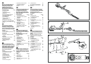
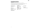
6. Operation (fig. H/I)
Voltage 12 V
Rated current (idling) 2 A
Strokes 2,100/min
Blade length 42 cm
Telescopic extension range 0 - 31 cm
Running time with Accu A 12 25 - 35 min
Weight (without Accu) 3.2 kg
Working area related emission
characteristic value
L
PA
1)
73 dB (A)
Noise level L
WA
2)
92 dB (A) Measuring method according to
Vibrations a
vhw
1)
< 2.5 dB (A)
1)
EN 774
2)
directive 2000/14/EC
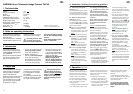
GARDENA Accu Telescopic Hedge Trimmer THS 42
1. Technical data
Please read these operating in-
structions carefully and observe
the notes given.
Use the instructions to familiarise
yourself with the equipment, the
operating controls, their correct
use, and the notes on safety.
A
For safety reasons, child-
ren under 16 as well as
persons not familiar with these
operating instructions should
not use this Telescopic Hedge
Trimmer.
Keep these operating instruc-
tions in a safe place.
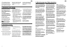
2. Notes on operating instructions
The GARDENA Accu Telescopic
Hedge Trimmer is designed for
trimming hedges in domestic
gardens and allotments.
Gardening tools for private house-
holds and gardens are consid-
ered unsuitable for use in public
grounds, parks, sports centres,
in agriculture or forestry.
Compliance with the instructions
provided by the manufacturer
is a prerequisite for using the
tool correctly.
The operating instructions also
include the conditions for opera-
tion, repair and maintenance.
A
Attention! Because of
the danger of physical
injuries, this tool must not be
used for cutting lawns / grass
verges, or for cutting in the
sense of shredding for com-
posting.
4. Proper use
This Hedge Trimmer is one of
the tools in the extensive range
of accu-system V12 equipment
from GARDENA.
Please use the following articles
from the accu-system V12 pro-
gramme to operate this tool:
1. Accu A 12 (Art. No. 2109) as
the energy supply / battery
for the accu-system V12.
2. Battery Charger NL 12
(Art. No. 2105) as the charger
for the accu-system V12.
Alternatively, the Accu-Pack
AP 12 (Art.-No. 2110) can be
used as the energy supply.
This can be recharged using
the Battery Charger NL 12
or by the High-speed Battery
Charger SL 60 which is avail-
able as an alternative.
Important! The High-speed
Battery Charger SL 60
(Art. No. 2100) is designed
only for charging the Accu-
Pack AP 12 (Art. No. 2110).
3. Introduction