


13
G
12
G
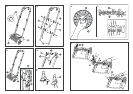
4.3 Assembling the
Guide Handle (Fig. B)
Warning! When assembling
the guide handle ensure that
the mains cable is free, that
it is not squashed in the
parts of the handle which are
connected and is not pulled.
Assemble the guide rail as
follows:
1. Guide the upper section of
the guide handle
2
into the
grooves in both sides of the
two middle sections of the
guide rail
3
.
2. Screw the upper section
2
to the middle sections of the
guide handle
3
using the wing
nuts and bolts provided
4
.
3. Clip the cable clip
5
with the
cable threaded through onto
the inner side of the guide
handle.
4. Guide both lower sections of
the guide handle
6
into the
grooves in the middle sections
3
of the guide handle.
5. Screw both lower sections of
the guide handle
6
to the
middle sections
3
using the
wing nuts
4
provided.
6. Insert the assembled guide
handle into the holes
J
, Fig. C.
7. Screw the assembled guide
handle from below to the
housing of the Lawn Scarifier
using the screws provided
H
(Fig. C/C1).
5.1 Connecting the Unit –
Cable Lock / Extension Cable
(Fig. D1)
1. First plug the extension cable
7
from below into the base
socket of the combination
switch/plug.
2. Loop the extension cable
7
and insert it into the cable lock
8
on the guide handle, allow
the lead to the socket to sag
a little.
Note: The cable lock prevents
unintentional disconnection
of the electricity.
Note:When in operation, the
mains cable must always be
guided in the direction you are
working at the side of the area
you are aerating. Always work
away from the mains cable.
5.2 Starting up (Fig.D)
1. Stand the scarifier on an even
part of the lawn.
Note: Always maintain the
safety distance from the
aerator indicated by the
length of the guide handle.
Danger of injury!
2. To start the scarifier, press
the release button
9
on the
switch/plug combination and
hold it down. At the same time,
pull the starting lever
0
with
the other hand towards the
handle.
3. When the motor is running, you
can release the release button
9
. If you release the starting
lever
0
the motor switches off.
Blockage Protection
If the aerator is blocked by a
foreign body or if the motor is
overloaded, the motor is auto-
matically switched off by the
blockage protection.Wait for
approx.1 minute and start the
scarifier again.
A
Warning! If you do not
release the starting lever
0
, the scarifier automatically
switches on again after approx.
1 minute. Danger of injury.
A
The safety devices in-
stalled on the scarifier
by GARDENA must not be
removed or bridged, e.g. by
tying the starting lever
0
to
the guide handle.The scarifier
can then no longer switch off
automatically. Danger of injury.
Warning! The aerator does
not stop immediately after the
motor has been turned off!
5. Putting into Operation
The aerator cylinder can be used
for removing matting and moss
in the lawn as well as for cutting
flat-rooting ranks.
6.1 Aerating
To maintain a well-cared-for
lawn we recommend aerating
every 4-6 weeks depending
on the state of your lawn.
1. First of all, mow your lawn to
the length you require.We
particularly recommend this
if the grass has grown tall
(e.g. while you were away on
holiday).
Recommendation: the
shorter you mow your lawn,
the easier it is to aerate,
thus lessening the strain on
the scarifier and increasing
the lifetime of the aerator.
Note: Remaining in one spot
for too long while aerating can
damage the grass.
2. For good results, guide the
Lawn Scarifier at an appropri-
ate speed in strips as straight
as possible across your lawn.
To prevent leaving gaps, the
strips should always overlap
by a few centimetres.
Warning! The rotating
A aerator can cause
injuries. Always push the
scarifier at a walking pace.
When working on inclines
always stand diagonally
to the incline in a sturdy,
safe stance. Do not work
on extremely steep slopes.
Danger of injury.
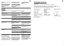
6. Correct Aerating
Power consumption 450 W
Voltage 230 V
Frequency 50/60 Hz
Working speed of the tool 2500 - 2800 rpm
Aerator width 30 cm
Working depth max. 4 mm
Working area related emission
characteristic value L
pA
1)
78 dB(A)
Noise level L
WA
2)
91 dB(A) Measuring method according to
Vibrations a
vhw
1)
≤ 2.5 ms
-2
1)
EN 60335-1
2)
directive 2000/14/EC
GARDENA Electric Lawn Scarifier ES 450/30
1. Technical Data
Please read and follow these
operating instructions carefully.
Familiarise yourself with the unit’s
features, its proper use and the
safety instructions included.
A
For safety reasons chil-
dren under the age of 16
or people not familiar with
these operating instructions
must not use this Electric
Lawn Scarifier.
Please keep these instructions
in a safe place.
2. Operating Instructions Information
The GARDENA Electric Lawn
Scarifier ES 450/30 is designed
for aerating lawns and grassy
areas in private domestic and
hobby gardens.
It is not designed for use in public
facilities, parks, sporting grounds,
on roads, in agriculture or forestry.
It is essential to observe the
manufacturer’s operating instruc-
tions to ensure the unit’s proper
functioning.
The operating instructions also
contain advice for service, main-
tenance and repair.
A
Attention! To prevent in-
jury, the Electric Lawn
Scarifier must not be used for
trimming bushes, hedges and
shrubs. In addition, the Electric
Lawn Scarifier must not be
used for levelling irregularities
in the soil.
3. Product use
4.1 Checking all the Parts
are Included
The Lawn Scarifier box contains
the following parts:
.Electric Lawn Scarifier
ES 450/30
.2 lower sections of the
guide handle
.2 middle sections of the
guide handle
.1 upper section of the
guide handle (frame with
switch/plug combination
and strain relief device)
.Assembly parts and
cable clip for guide handle
in a plastic bag
.Operating instructions
4.2 Operating Parts
1
Lawn scarifier housing
2
Upper section of the
guide handle
3
Middle sections of the
guide handle
4
Wing nuts with bolts
5
Cable clip
6
Lower sections of the
guide handle
7
Extension cable
(not included)
8
Cable relief device
9
Release knob
0
Starting lever
A
Wheels
B
Springs
C
Adjustment unit
D
Wheel with end plate
E
Aerator
F
Screws for end plate
G
Retaining spring
H
Screws for guide handle
I
Drive shaft
(receptacle square bar)
J
Receptacle holes
K
Switch/plug combination
4. Assembly