


g
3
S
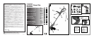
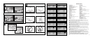
PRODUCT DESCRIPTION (Fig. 0)
1. Supply cord retainer
2. Rear handle
3. Assist handle lock buttons
4. Air vents
5. Debris shield
6. Cutting line head
7. Edging guide / line protector
8. Motor housing
9. Adjustable shaft
10. Shaft locking button
11. Assist handle
12. On/Off trigger
13. Mains cable
a
SAFETY MARKINGS
The following symbols on your trimmer are intended to remind you of some of the most important
safety precautions:
1. WARNING. This product is potentially dangerous. Take great care at all times to avoid injury.
2. Read the operator’s manual.
3. Disconnect the mains plug if the cord is damaged.
4. Wear eye protection at all times.
5.
Approved ear defender.
6. Do not work near bystanders.
7. Do not use in rain or damp conditions.
8. LWA indicates the noise power level. Wear ear plugs or mufflers if necessary.
9. indicates that the product conforms to the relevant European Directives as required by law.
b
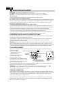
ASSEMBLY
DEBRIS SHIELD INSTALLATION
Fig. 2-1
1. Position the motor housing with string head carrier facing up.
2. Slide debris shield over motor housing as shown.
Fig. 2-2
3. Align edging guide with mating grooves and push firmly in the direction shown until an audible
snap is heard.
NOTE: Be certain that edging guide is oriented as shown. Once edging guide, motor housing and
debris shield are mated the connection is permanent and cannot be removed without a special tool.
EXCHANGE OF SPOOL
Turn off the machine and disconnect the plug from power supply. Wait until nylonline has come to a
complete stop. Pict. 2-3 Press both press-buttons 1 and lift off the cover 2. Pict. 2-4 Replace the empty
spool 3 by inserting each line end through the eyelets as shown. Secure the spool with a slight turn to
ensure correct position in the base plate. Then replace the cover ensuring both press-buttons lock in.
NOTE: The complete spool and line must be replaced and line must be replaced and is available as
an accessory.
c
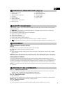
PRODUCT ADJUSTMENTS
Fig. 3-1 - Adjustment Assist Handle
1. Using thumb and forefinger push in both spring loaded lock buttons at the base of the assist
handle in order to release the ratchet adjustment mechanism.
2. Adjust handle as necessary and release automatic lock buttons.
Fig. 3-2 - Adjust Shaft Length
1. Grip shaft firmly.
2. Push red shaft release button forward and move handle forward or backward to desired length.
NOTE: Shaft may be adjusted in trimming or edging mode.
Fig. 3-3 - Edging Conversion
1. Grip shaft firmly.
2. Push red button forward and rotate handle assembly until an audible click is heard.