


Installation Instructions 1846197
2
© Copyright 2000 Ferris Industries. All Rights Reserved.
7. Block the front wheels and jack up the rear of the
machine and set on jack stands or wooden blocks.
Remove the left drive tire. This will allow for easier
access to the left hand pump.
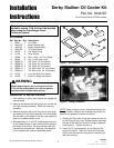
8. Remove the left return hose and loosen the jam nut
on the fitting on the pump. Rotate the fitting towards
the rear of the machine and point it slightly upwards
(see Figure 2). Tighten the jam nut.
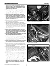
9. Install the 25” hose assembly to the fitting on the
pump and tighten. Leave the free end of the hose
higher than the reservoir to prevent to hydraulic sys-
tem from draining. Route the hose behind the high-
pressure hoses (see Figure 3).
10. Remove both return hoses from the top of the reser-
voir and save the hose clamps.
11. Reinstall the control cross shaft into the saddles.
Make sure the new hoses do not contact the shaft. If
the hose does contact the shaft, loosen the jam nut
on the fitting and rotate the fitting until approximately
1/4” clearance is obtained. Secure the cross shaft
with the split collars.
12. Route the 48” hoses under the control cross shaft
and through the clearance opening in the battery pan
near the right-hand pump, under the wiring harness
and under the 5/8” supply hose.
13. Connect the return hoses to the reservoir and secure
with the hose clamps previously removed.
14. Install the oil coolers in the oil cooler mount using the
torx bolts and nylon nuts supplied with this kit. Make
sure the hose barbs of the coolers are pointing
towards the half-holes in the mount.
15. Install the left and right side cooler mount brackets to
the fuel tanks using the bolts previously removed.
16. Install the oil cooler mount on the brackets, center
side-to-side and secure with the torx bolts and nylon
nuts previously removed.
17. Connect the hoses the the oil coolers. Connect the
hose from the right side barb of the oil reservoir to
the right side oil cooler and the hose from the left
side barb to the left side cooler. See Figure 4 for the
proper hose locations. Secure with the enclosed
hose clamps.
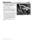
18. Install the tie wraps as shown in Figures 4-6. Use a
long tie wrap to secure the 48” hoses to the 5/8” sup-
ply hose. Position the hoses so the do not contact
the battery pan. Use the remaining two long tie
wraps the bundle the hoses together in front of the
engine. Be sure the tie wrap the hoses to the engine
screen. Use the short tie wrap to secure the 25”
hose to the engine oil dipstick tube. Do not over-
tighten the tie wraps or collapsing the hose may
result.
Figure 3. Left Return Hose Routing
Figure 4. Hose Routing
Tie Wrap
Figure 5. Tie Wrap Location