


39
SEAT ADJUSTMENT
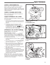
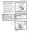
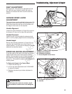
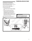
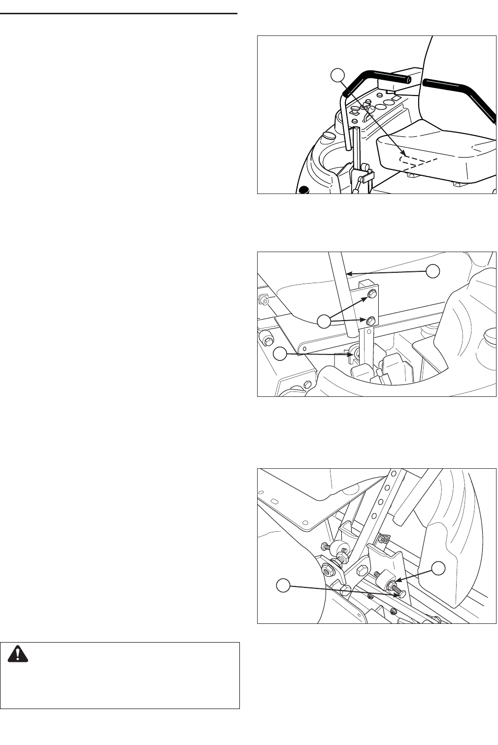
See Figure 29. The seat can be adjusted fore and
aft. Move the lever forward, position the seat as
desired, and release the lever to lock the seat into
position.
GROUND SPEED LEVER
ADJUSTMENT
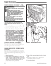
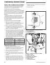
The control levers can be adjusted in three ways. The
alignment of the control levers, the placement of the
levers (how close the ends are to one another) and
the height of the levers can be adjusted.
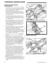
Handle Alignment
Loosen the mount hardware (A, Figure 30) and pivot
the lever(s) (C) fore or aft to align with each other.
Handle Placement
Loosen the jam nuts and adjust the placement bolt
(B) in or out to properly adjust the lever end spacing.
Handle Height
Remove the mounting hardware (A, Figure 30) and
reposition the handle either up or down from its
original position. You will need to readjust the handle
alignment as described above.
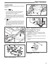
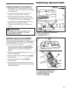
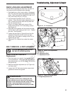
SPEED BALANCING ADJUSTMENT
If the rider veers to the right or left when the ground
speed control levers are in the maximum forward
position, the top speed of each of these levers can
be balanced by turning the adjustment bolt(s) (A,
Figure 31). Only adjust the speed of the wheel that is
traveling faster.
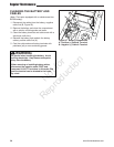
To Reduce the Speed of the Faster Wheel
1. Loosen the securing nut.
2. turn the top speed adjustment bolt CLOCKWISE
to reduce the speed.
3. Retighten the securing nut when adjustment is
complete.
WARNING
DO NOT adjust the tractor for a faster overall
speed forward or reverse than it was designed
for.
Figure 29. Seat Adjustment
A. Seat Adjustment Lever
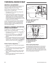
Figure 30. Control Lever Adjustment
A. Alignment Hardware
B. Placement Hardware
C. Ground Speed Control Lever
B
C
A
Figure 31. Top Speed Adjustment
A. Top Speed Adjustment Bolt
B. Jam Nut
A
B
A
Troubleshooting, Adjustment & Repair
Not for
Reproduction