43
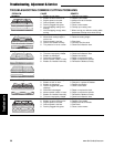
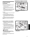
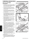
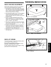
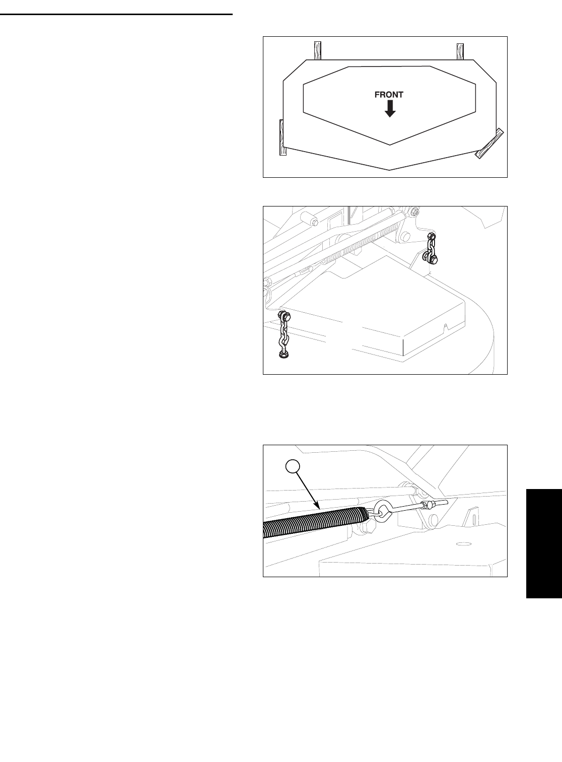
Figure 41. 2 x 4 Locations
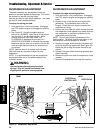
Figure 42. Hanger Chain Adjustment
DECK LEVELING ADJUSTMENT
NOTE: Before adjusting the deck level, the deck lift
rod timing must be checked and/or adjusted.
1. Park machine on a flat, level surface. Disengage
the PTO, stop the engine and engage the parking
brake. Rear tires must be inflated to 15 psi (1,03
bar); front tires to 25 psi (1,72 bar).
2. Lock the deck lift pedal in the 5” (12,7cm) position.
Place the deck height adjustment pin in the 4"
position and lower deck the lift pedal until the arm
contacts the pin.
3. Place 2 x 4 blocks under each corner of the
mower deck with the 3-1/2” sides being vertical.
Place a 1/4” (0,64cm) thick spacer on top of the
rear 2 x 4 blocks. See Figure 41.
4. Adjust the front eyebolts until the chains are tight
and the deck is still resting on the 2 x 4’s. Tighten
jam nuts. See Figure 42.
5. Loosen the nuts and allow the rear of the deck to
rest on the 2 x 4’s and 1/4” spacers. Slide the
chains down in the slots until the chains are tight
and tighten the nuts. See Figure 42.
6. Remove all 2 x 4 blocks and spacers from under
the mower deck.
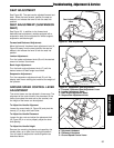
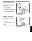
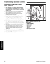
Figure 43. Deck Lift Spring Location
A. Deck Lift Spring
DECK LIFT SPRING
The deck lift springs (A, Figure 43) are factory set to
provide optimal lifting performance.
Although it is fastened with a multi-position anchor,
this is NOT AN ADJUSTMENT POINT.
DO NOT attempt to adjust the spring length or lifting
performance will be compromised.
Adjust
Here
Adjust
Here
Troubleshooting, Adjustment & Service
Troubleshooting
A


