


Maintenance
Adjustments
Note: Disengage PTO, shut off engine, wait for
all moving parts to stop, engage parking brake, and
remove key before servicing, cleaning, or making any
adjustments to the unit.
Deck Leveling
See Adjusting the Cutting Height section in
Operation.
Pump Drive Belt Tension
Self-tensioning - No adjustment necessary.
PTO Clutching Belt Tension
See Inspect PTO Clutching Belt Tension section.
Deck Belt Tension
Self-tensioning - No adjustment necessary.
Park Brake Adjustment
1. Shut off engine and wait for all moving parts to
stop.
2. Disengage the park brake.
3. Remove the hairpin in the park brake linkage.
Turn the linkage in the yoke until there is 3/16
inch (4.8 mm) to 1/4 inch (6.4 mm) clearance
between the park brake tire bars and the tires with
the park brake disengaged. Re-install the hairpin.
Hydro Drive Linkage
Adjustment
• Adjust Speed Control Linkage and Neutral
Safety Switch:
1. Stop engine and wait for all moving parts to
stop. Engage parking brake. Remove key or
spark plug wire(s).
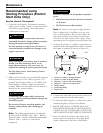
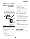
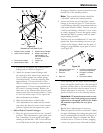
2. Move the speed control lever (located on
the console) to the full forward position and
check the orientation of the tabs on the ends
of the speed control crank (see
Figure 18).
These tabs should be pointing straight down
at the 6 o’clock position or slightly forward.
Adjust the threaded yoke at the bottom of the
speed control linkage (see Figure 18) until the
tabs are positioned correctly.
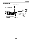
Figure 18
Viewed from Left Side of Unit
1. Neutral Safety Switch 3. 5/16 inch (7.9 mm)
2. Actuating Tab in neutral
position
3. Pull the speed control lever back to neutral.
Check that the neutral safety switch actuating
tab has depressed the plunger of the switch
so that there is about 5/16 inch (7.9 mm)
between the tab and the switch (see
Figure 18).
If necessary, move the switch fore and aft.
• Adjust Neutral Control Linkages:
1. Raise the rear of the machine up onto jack
stands high enough to raise the drive wheels
off of the ground.
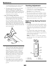
2. Start the engine and move the throttle ahead
to the full throttle position. Place the neutral
lock latches in the “forward” position as
shown in
Figure 4. Release the park brake
and move the speed control lever to the
“mid-speed” position.
Note: The OPC levers must be held down
and the park brake must be disengaged
whenever the speed control lever is moved
out of neutral or the engine will kill.
3. Squeeze the respective drive lever until an
increased resistance is felt, this is where
neutral should be.
If the wheel turns while holding the drive
lever in neutral, the neutral control linkages
need to be adjusted. If the wheel stops then
go to step 7.
34