


- 16 -
3.12 Connect the lower end of the speed control linkage to the speed control crank
located at the top rear of the fuel tank support. Secure with clevis pin and hairpin
from the bolt bag.
3.13 Install drive lever linkages.
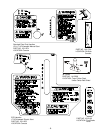
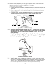
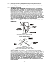
For Standard Pistol Grip Handles: Refer to figures 4 and 5. Position speed
control lever in neutral. Locate two long clevis pins and two hairpin cotters in bolt
bag and temporarily install through drive levers and neutral lock latches, but not
through the drive lever linkages. Position drive levers and neutral lock latches in
neutral (See Figure 16). Identify swivels installed on hydro control arm weldments.
Thread each drive lever linkage into swivel until hole in upper end of drive lever
linkage aligns with clevis pin installed through drive lever and neutral lock latch.
Remove clevis pins and install first through the drive lever linkages, then through the
drive levers from the outside , then through the neutral lock latches. Install hairpin.
This will give an approximate setting for drive lever linkages; you will need to refer to
Section 5.2.6 step d to complete the drive lever linkage adjustment.
NOTE: There should NOT be a washer between the neutral lock latch and the
hairpin cotter.
FIGURE 4
STANDARD PISTOL GRIP HANDLES
DRIVE LINKAGE SWIVEL
FIGURE 5
STANDARD PISTOL GRIP HANDLES
DRIVE LEVER LINKAGE TO DRIVE LEVER
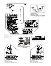
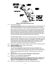
For ECS handles: Refer to figure 6. Position speed control lever in neutral.
Position drive levers in neutral and engage the neutral lock latches (See Figure 16).
Drive lever linkages are shipped with upper ball joints installed. Thread a 3/8-24 LH
jam nut, from the bolt bag, onto the lower end of each drive lever linkage. Identify
the lower ball joints installed on hydro control arm weldments. Thread lower end of
each drive lever linkage into the lower ball joint until hole in upper ball joint aligns
with hole in drive lever. Install 3/8-16 x 2 hex cap screws and 3/8-16 nyloc nuts from
the bolt bag and tighten. This will give an approximate setting for drive lever
linkages; you will need to refer to Section 5.2.6 step d to complete the drive lever
linkage adjustment.