


- 33 -
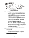
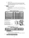
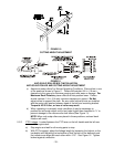
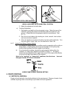
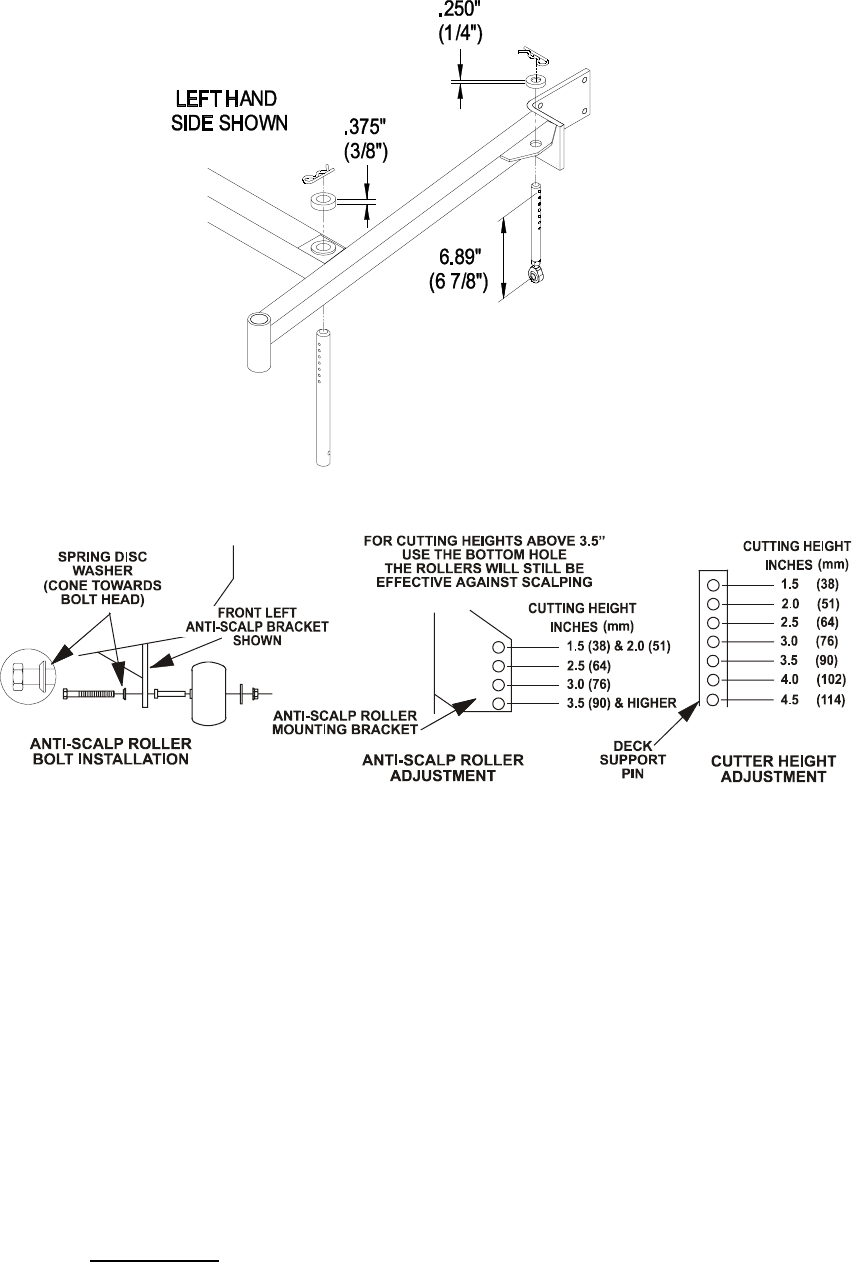
FIGURE 10
CUTTING HEIGHT ADJUSTMENT
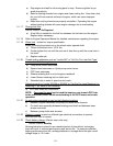
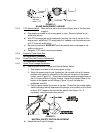
FIGURE 11
ANTI-SCALP ROLLER BOLT INSTALLATION
ANTI-SCALP ROLLER AND CUTTING HEIGHT ADJUSTMENT
c) Adjust anti-scalp rollers For Normal Operating Conditions. Place rollers in one
of the positions shown in Figure 11. Rollers will maintain 3/4 in. (19 mm)
clearance to the ground to minimize gouging and roller wear or damage. For
Maximum Deck Flotation, place rollers one hole position lower. Rollers
should maintain 1/4 in. (6.4 mm) minimum clearance to ground. Do Not
adjust rollers to support the deck. Be sure roller bolts and nuts are installed
with the spring disc washer between head of the bolt and mounting bracket.
Torque to 40-45 ft-lbs., or loss of roller may result.
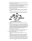
d) When operating in extremely rough conditions it may be necessary to
position the anti-scalp rollers one or two holes higher than described in "c" to
prevent damage to the rollers and/or bolt failure (See Figure 11).
NOTE: When anti-scalp rollers are placed in these positions, reduced deck
flotation will result.
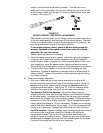
5.2.2 PTO Linkage: Located between the PTO lever on the left handle and the left rear
corner of the engine deck.
a) Stop engine and wait for all moving parts to stop.
b) With PTO engaged, adjust the linkage length by loosening the locknut on the
turnbuckle and adjusting the turnbuckle so that the bolt on the bellcrank and
the indicator arm align with each other within 1/16”. See Figure 12. Tighten
locknut against turnbuckle.