


Maintenance
control linkage until tabs are positioned correctly.
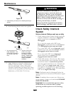
See Figure 14.
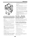
3. Pull speed control lever back to neutral. Check
that the neutral safety switch actuating tab has
depressed the plunger of the switch so that there
is about 5/16 inch (7.9 mm) between the tab and
the switch as shown in Figure 14. If necessary,
move the switch fore and aft.
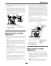
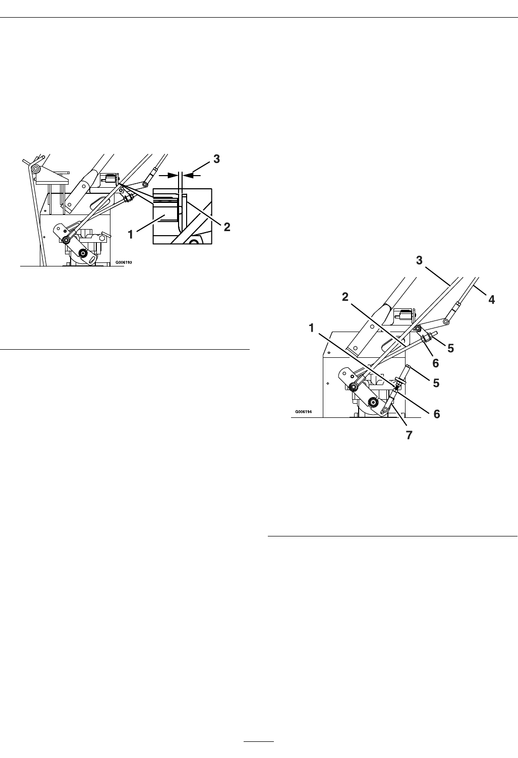
Figure 14
Viewed from left side of unit
1. Neutral Safety Switch 3. 5/16 inch (7.9 mm)
2. Actuating Tab in neutral
position
Neutral Control Linkages
Adjustment
1. Raise the rear of the machine up onto jack stands
high enough to raise the drive wheels off of the
ground.
2. Start the engine and move the throttle ahead to
the full throttle position. Place the neutral lock
latches in the “forward” position as shown in
Figure 4 and move the speed control lever to the
“mid-speed” position.
Note: The park brake must be disengaged and
the OPC levers must be held down whenever the
speed control lever is out of the neutral position
or the engine will kill.
3. Squeeze the respective drive lever until an
increased resistance is felt; this is where neutral
should be.
If the wheel turns while holding the drive lever in
neutral, the neutral control linkages need to be
adjusted. If wheels stop then go to step 7.
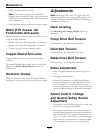
4. Loosen the nut against the neutral control linkage
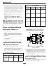
yoke as shown in Figure 15
5. Adjust the neutral control linkage until the
respective drive wheel stops when the lever is
pulled against the neutral spring (neutral position).
Turn the adjusting bolt approximately 1/4 turn
clockwise if the wheel is turning in reverse or turn
the bolt approximately 1/4 turn counterclockwise
if the wheel is turning forward. Release the drive
lever to the forward drive position and squeeze
back into the neutral position. Check to see if the
wheel stops. If not, repeat the above adjustment
procedure.
6. Make this adjustment on both sides.
7. After adjustments are made and the wheels stop
when the drive lever is in the neutral position,
tighten the nut against the yokes.
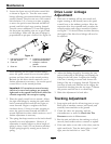
Figure 15
1. Neutral Control Linkage
5. Adjust here; rotate at
approximately 1/4 turn
increments
2. Hydro Control Linkage
6. Loosen nut
3. Drive Lever Linkage 7. Yoke
4. Speed Control Linkage
Hydro Control Linkage
Adjustment
1. Place the speed control lever in the “neutral”
position. This adjustment is again made with rear
of machine on jack stands and engine running
at full throttle. OPC levers will have to be held
down whenever speed control lever is moved out
of neutral position.
Note: The neutral lock latches should still be
“unlocked” and in the “forward” position.
31