


Operation
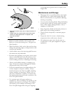
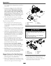
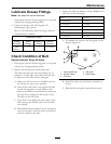
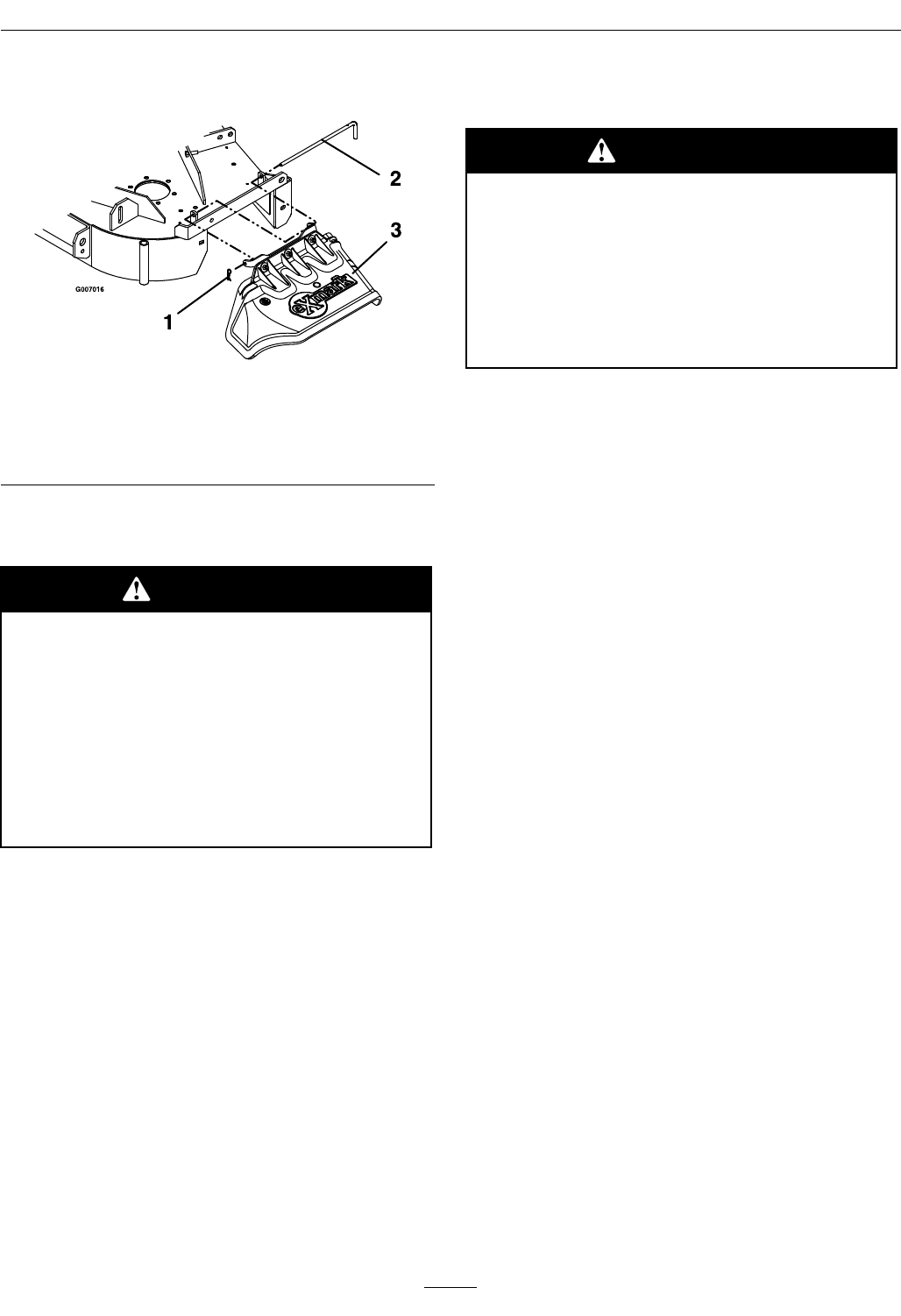
6. Install the discharge chute using the chute pivot
pin and hairpin (see Figure 7).
Figure 7
Viewed from the right side
1. Hairpin 3. Discharge chute
2. Chute pivot pin
Note: Install chute with the tabs to the rear of
the deck tabs as shown.
WARNING
An uncovered discharge opening will
allow objects to be thrown in operator’s or
bystander’s direction. Also, contact with
blade could occur. Thrown objects or blade
contact can cause serious injury or kill you
or bystanders.
Never operate mower unless discharge
deector, or entire grass collection system, or
mulch kit is installed.
7. Re-install the plastic belt cover and tighten the
knobs.
8. Remove the hair pins and clevis pins holding the
hopper assembly to the mount weldment.
9. Lift the hopper assembly off the mount.
10. Remove the hairpins and lift the front weights off
of the mount plate.
Note: The removable weights are heavy. Use
care when lifting them. Make sure that you can
hold them securely before lifting them. Use
caution when positioning your hands so that you
Do Not set them down on your hands or ngers.
Note: The portions of the Ultra Vac bagger that
are not bolted to the mower are designed to be
installed or removed in their entirety. Do Not
operate the mower with only a portion of the
Ultra Vac installed.
WARNING
Caster or front oor pan weights installed
without bagger may cause loss of traction
and steering control. Loss of control can
result in an accident, which may cause death,
injury, or property damage.
Install caster or front oor pan weights
ONLY when bagger is installed.
11. The machine can now be used for side discharge
mowing.
Bagger Installation for Bagging
1. Stop engine, remove key, and wait for all moving
parts to stop.
2. Remove hairpin and chute pivot pin. Remove
discharge chute. Pivot pin and hair pin may be
stored in the pivot holes of the discharge chute
during bagging operation.
3. Slide tube ends of hopper assembly into the tubes
of the mount weldment (see Figure 5). Install two
clevis pins through holes in tubes. Retain with
two hair pins.
4. Remove the belt cover on the right side of the
deck (see Figure 6). Install the blower by inserting
the mounting pin into the tube welded to the rear
corner of the deck. Pivot the blower until the
front pin engages the slot in the deck. Adjust the
position of the front pin if necessary to engage
the slot. Use the latch to lock the blower in this
position.
5. Pull the idler release handle and install the belt in
the upper groove of the deck sheave.
6. Install the belt cover using the two knobs.
7. Install the discharge tube assembly by slipping the
upper end into the hood, then sliding the lower
end over the blower discharge opening. Use the
latches to retain the lower end to the blower.
8. For Units Serial Number 600,000 and Higher
with Triton Decks: Adjust position of dog leg
bafe to match the intake of the Ultra Vac blower
bafe adjusted too wide may allow objects to be
thrown from under deck. Bafe adjusted too
narrow may cause plugging issues.
13